TPC Command for Scheduled PUSCH
Downlink Assignment Index (DAI)
Antenna Ports and Scrambling ID
TPMI Information for Precoding
PMI Confirmation for Precoding
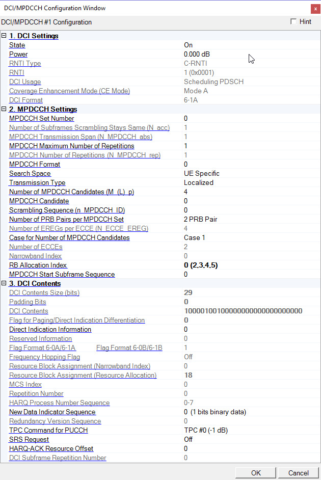
For DCI/MPDCCH #1 for DL-SCH1 Scheduling:
Choice: Off | On
Default: On
Double-click or use the drop-down menu to turn the channel on or off.
For :DCI/MPDCCH #2 - #8 for DL-SCHn Scheduling and DCI/MPDCCH for Other Control:
Choice: Off | On
Default: Off
Double-click or use the drop-down menu to turn the channel on or off
Range: -60.000 to 20.000 dB
Default: 0.000 dB
Enter the power level in dB for the channel.
For DCI/MPDCCH for DL-SCH Scheduling:
Displays RNTI Type. The value is same as corresponding DL-SCH RNTI Type.
For DCI/MPDCCH for Other Control:
Choice: C-RNTI | TPC-PUCCH-RNTI | TPC-PUSCH-RNTI
Default: C-RNTI
Double-click or use the drop-down menu to select RNTI Type.
For DCI/MPDCCH for DL-SCH Scheduling:
Display RNTI. RNTI is the same value as corresponding DL-SCH RNTI.
Example: The decimal input "15" is displayed as "15 (0x000F)" and the hexadecimal input "0xf" is displayed as "15 (0x000F)".
For more information, refer to 3GPP TS 36.212 5.3.3.2 and 36.321 7.1.
For DCI/MPDCCH for Other Control:
Range:
0 to 65533 (when RNTI Type is C-RNTI) (See Note)
1 to 65523 (when RNTI Type is TPC-PUCCH-RNTI)
1 to 65523 (when RNTI Type is TPC-PUSCH-RNTI)
Default: 1 (0x0001)
Enter the Radio Network Temporary Identifier (RNTI) for the channel.
Available input methods are the decimal format and hexadecimal format.
According to the standard, the range of C-RNTI is 1 to 65523, but the range 0 to 65533 is available for flexible use case.
Example: The decimal input "15" is displayed as "15 (0x000F)" and the hexadecimal input "0xf" is displayed as "15 (0x000F)".
For more information, refer to 3GPP TS 36.212 5.3.3.2 and 36.321 7.1.
For DCI/MPDCCH for DL-SCH Scheduling:
Choice:
Paging | Direct Indication (when RNTI Type is P-RNTI)
Scheduling PDSCH (read-only) (when RNTI Type is C-RNTI)
Random Access Response (read-only) (when RNTI Type is RA-RNTI)
N/A (read-only) (when RNTI Type is N/A)
Default: Scheduling PDSCH (read-only)
Coupling: When RNTI Type is C-RNTI, RA-RNTI or N/A, this is read-only.
Double-click or use the drop-down menu to select DCI Usage.
For more information, refer to 3GPP TS 36.212 5.3.3.1.10 to 5.3.3.1.14.
For DCI/MPDCCH for Other Control:
Choice:
Scheduling PUSCH | During Random Access Procedure | PDCCH order to initiate Random Access Procedure (when RNTI Type is C-RNTI)
Uplink Power Control (read-only) (when RNTI Type is TPC-PUCCH-RNTI or TPC-PUSCH-RNTI)
Default: Scheduling PUSCH
Coupling: When RNTI Type is TPC-PUCCH-RNT or TPC-PUSCH-RNTI, this is read-only.
Double-click or use the drop-down menu to select DCI Usage.
For more information, refer to 3GPP TS 36.212 5.3.3.1.10 to 5.3.3.1.14.
Choice: Mode A | Mode B
Default: Mode A
Coupling: This parameter linked to the CE Mode of DL-SCH.
Display Coverage Enhancement Mode (CE Mode).
For more information, refer to 3GPP TS 36.211, 36.213 and 36.331.
For DCI/MPDCCH for DL-SCH Scheduling:
Choice:
6-1A (read-only) (when RNTI Type is C-RNTI or RA-RNTI, and corresponding DL-SCH CE Mode is Mode A)
6-1B (read-only) (when RNTI Type is C-RNTI or RA-RNTI, and corresponding DL-SCH CE Mode is Mode B)
6-2 (read-only) (when RNTI Type is P-RNTI)
N/A (read-only) (when RNTI Type is SI-RNTI)
Default: 6-1A (read-only)
Displays DCI Format which is determined by related parameters such as Transmission Mode of DL-SCH, RNTI Type of DLSCH, DCI Usage and, RNTI Type of DCI.
For more information, refer to 3GPP TS 36.212 5.3.3.1.10 to 5.3.3.1.14.
For DCI/MPDCCH for Other Control:
Choice:
3 | 3A (when RNTI Type is TPC-PUCCH-RNTI or TPC-PUSCH-RNTI)
6-0A (read-only) (when RNTI Type is C-RNTI and CE Mode is Mode A)
6-0B (read-only) (when RNTI Type is C-RNTI and CE Mode is Mode B)
6-1A (read-only) (when RNTI Type is C-RNTI, CE Mode is Mode A, and DCI Usage is PDCCH order to initiate Random Access Procedure)
6-1B (read-only) (when RNTI Type is C-RNTI, CE Mode is Mode B, and DCI Usage is PDCCH order to initiate Random Access Procedure)
Default: 6-0A (read-only)
Double-click or use the drop-down menu to select DCI Format.
For more information, refer to 3GPP TS 36.212 5.3.3.1.10 to 5.3.3.1.14.
Choice: 0 | 1
Default: 0
Coupling: If MPDCCH Format is 5, this parameter is set to 0 and read-only.
Double-click or use the drop-down menu to select MPDCCH set number (MPDCCH-PRB-set).
For more information, refer to 3GPP TS 36.213 9.1.4.4 and 9.1.5.
Coupling: This parameter is visible only when UE Type is set to BL/CE.
Displays the number of consecutive absolute subframes over which the scrambling sequence stays the same (N_acc).
If RNTI Type is P-RNTI, this is set to 4. Otherwise this is set to 1 for CE Mode A or 4 for CE Mode B.
For more information, refer to 3GPP TS36.211.
Displays the number of consecutive subframes including invalid subframes where the UE postpones the MPDCCH transmission for BL/CE UE.
For more information, refer to 3GPP TS 36.211 6.8B.2 and 6.10.3A.1 for more information.
Choice: 1 | 2 | 4 | 8 | 16 | 32 | 64 | 128 | 256
Default: 1
Double-click or use the drop-down menu to select the maximum number of repetitions for MPDCCH.
For more information, refer to 3GPP TS 36.211 6.8B.1 and 36.331 6.3.2.
Displays MPDCCH Number of Repetitions (Repetition Level) which is determined by MPDCCH Maximum Number of Repetitions and Search Space.
r1, r2, r3, r4 are determined by substituting the value of r_max with the value of MPDCCH Maximum Number of Repetitions parameter36.213 Table 9.1.5-3 when Search Space is UE Specific, Type 0 Common, or Type 2 Common.
r1, r2, r3, r4 are determined by substituting the value of r_max with the value of MPDCCH Maximum Number of Repetitions parameter 36.213 Table 9.1.5-4when Search Space is Type 1 Common.
For more information, refer to 3GPP TS 36.213 9.1.5.
Choice:
MPDCCH Max Number of Repetitions = 1:
0 | 1 | 2 (when Number of PRB Pairs per MPDCCH Set is 2 PRB Pair and Case for Number of MPDCCH Candidates is other than Case 3)
0 | 1 | 2 | 3 (when Number of PRB Pairs per MPDCCH Set is 2 PRB Pair and Case for Number of MPDCCH Candidates is Case 3 or Number of PRB Pairs per MPDCCH Set is 4 PRB Pair and Case for Number of MPDCCH Candidates is other than Case 3)
0 | 1 | 2 | 3 | 4 (when Number of PRB Pairs per MPDCCH Set is 4 PRB Pair and Case for Number of MPDCCH Candidates is Case 3)
0 | 1 | 2 | 3 | 5 (when Number of PRB Pairs per MPDCCH Set is 2 + 4 PRB Pairs)
MPDCCH Max Number of Repetitions > 1
0 | 1 | 2 (when Number of PRB Pairs per MPDCCH Set is 2 PRB Pair)
0 | 1 | 2 | 3 (when Number of PRB Pairs per MPDCCH Set is 4 PRB Pair)
0 | 1 | 2 | 3 | 5 (when Number of PRB Pairs per MPDCCH Set is 2 + 4 PRB Pairs)
Default: 0
Double-click or use the drop-down menu to select MPDCCH Format.
For more information, refer to 3GPP TS36.211 6.8A.1 and 6.8B.1.
For DCI/MPDCCH for DL-SCH Scheduling:
Choice:
Type0 Common | UE Specific (when RNTI Type is C-RNTI, corresponding DL-SCH CE Mode is A and Transmission Mode is 1 or 2)
UE Sepcific | Type0-Common | Type1-Common | Type2-Common | N/A (read only and determined by other parameters)
Default: UE Specific
Double-click or use the drop-down menu to select MPDCCH Search Space.
For more information, refer to 3GPP TS36.213 9.1.5.
For DCI/MPDCCH for Other Control:
Choice:
Type0 Common | UE Specific (when RNTI Type is C-RNTI, CE Mode is A, and DCI Usage is Scheduling PUSCH or PDCCH order to initiate Random Access Procedure)
UE Specific | Type0 -Common | Type2-Common (read only and determined by other parameters)
Default: UE Specific
Double-click or use the drop-down menu to select MPDCCH Search Space
For more information, refer to 3GPP TS36.213 9.1.5.
Choice: Localized | Distributed
Default: Localized
Double-click or use the drop-down menu to select MPDCCH Transmission Type whether distributed or localized transmission.
For more information, refer to 3GPP TS 36.211 6.8A.1, 6.8B.1 and 36.213 9.1.5.
Range: 1 to 8
Default: 4
Enter Number of MPDCCH Candidates (M_(L)_p).
For more information, refer to 3GPP TS 36.213 9.1.4 and 9.1.5.
Range: 0 to Number of MPDCCH Candidates - 1 (it depends on relative parameters)
Default: 0
Enter MPDCCH Candidate.
For more information, refer to 3GPP TS 36.213 9.1.4 and 9.1.5.
Range: 0 to 503
Default: 0
Enter the scrambling sequence initialization parameter (n_MPDCCH_ID).
For more information, refer to 3GPP TS 36.211 6.10.3A.1, and 36.331 6.3.2.
Choice: 2 PRB Pair | 4 PRB Pair | 2 + 4 PRB Pairs
Default: 2 PRB Pair
Double-click or use the drop-down menu to select the number of physical resource-block pairs used for the MPDCCH set.
For more information, refer to 3GPP TS 36.211 6.8A.1, 6.8B.1 and 36.213 9.1.5.
Displays Number of EREGs per ECCE.
Number of EREGs per ECCE is set to 4 and 8 for normal and extended cyclic prefix, respectively.
For more information, refer to 3GPP TS36.211 6.8A.1 and 6.8B.1.
Choice:
Case 1 | Case 3 (when Cyclic Prefix is Normal)
Case 2 (when Cyclic Prefix is Extended)
Default: Case 1
Coupling: When Cyclic Prefix is set to Extended, this parameter is fixed to Case 2 and read-only.
Double-click or use the drop-down menu to select Case for Number of MPDCCH Candidates.
For more information, refer to 3GPP TS36.211 Table 6.8A.1-2 and 36.213 9.1.4.
Displays Number of ECCEs.
MPDCCH is transmitted using an aggregation of one or several consecutive enhanced control channel elements (ECCEs) where each ECCE consists of multiple enhanced resource element groups (EREGs).
MPDCCH Number of ECCEs depends on MPDCCH Number of Repetitions, CEMode, Transmission Type and Case for Number of ECCEs.
For more information, refer to 3GPP TS36.211 Table 6.8A.1-1 and Table 6.8B.1-2.
Range:
1.4 MHz: 0
3 MHz: 0 to 1
5 MHz: 0 to 3
10 MHz: 0 to 7
15 MHz: 0 to 11
20 MHz: 0 to 15
Default: 0
Enter the narrowband index when DCI/MPDCCH is for Other Control.
Displays the narrowband index same value as the corresponding DL-SCH when DCI/MPDCCH is for DL-SCH Scheduling.
For more information, refer to 3GPP TS 36.211 6.8B.5 and 36.331 6.3.2.
Range:
2 or 4 PRB Pair: 0 to 14
2 + 4 PRB Pairs: 0
Default: 0
Enter RB Allocation Index of Narrowband Index for MPDCCH.
Display PRBs of the Narrowband Index in parentheses after RB allocation index.
For more information, refer to 3GPP TS 36.213 9.1.4.4.
Range: 0 to 10239
Default: 0
Enter the starting subframe of MPDCCH.
The input of multiple numbers is available to enable multiple MPDCCH transmissions.
Each value indicates the start subframe for each MPDCCH transmissions.
The input of comma separated values(ex. "1, 2, 3") and / or hyphen separated value(ex. "1-3") is available.
The input value check is executed before signal generation, and an error message is shown if input is not correct.
Coupling: This parameter is visible only when UE Type is set to BL/CE.
Displays the DCI contents size (bits) which is transport block size of DCI.
For more information, refer to 3GPP TS 36.212 5.3.3.1.10 to 5.3.3.1.14.
Displays the padding bits in DCI contents.
For more information, refer to 3GPP TS 36.212 5.3.3.1.10 to 5.3.3.1.14.
Coupling: This parameter is visible only when UE Type is set to BL/CE.
Displays the DCI contents.
For more information, refer to 3GPP TS 36.212 5.3.3.1.10 to 5.3.3.1.14.
Coupling: This parameter is read-only when DCI Format is set to 6-0A or 6-1A. Otherwise invisible.
Displays the flag DCI format 6-0A/format 6-1A differentiation, where value 0 indicates format 6-0A and value 1 indicates format 6-1A.
For more information, refer to 3GPP TS 36.212 5.3.3.1.10 and 5.3.3.1.12.
Coupling: This parameter is read-only when DCI Format is set to 6-0B or 6-1B. Otherwise invisible.
Displays the flag DCI format 6-0B/format 6-1B differentiation, where value 0 indicates format 6-0B and value 1 indicates format 6-1B.
For more information, refer to 3GPP TS 36.212 5.3.3.1.10 and 5.3.3.1.12
Coupling: When DCI Format is Format 6-2, this is visible
Display the flag for Paging/Direct Indication Differentiation, where value 0 and 1 indicate Direct Indication and Paging respectively.
This parameter is visible when DCI Format is Format 6-2.
For more information, refer to 3GPP TS36.212.5.3.3.1.14.
Range: 0 to 255
Default: 0
Coupling: When DCI Usage is Direct Indication Information, this is visible.
Enter a value of Direct Indication Information.
For more information, refer to 3GPP TS36.212.5.3.3.1.14.
Coupling: This parameter is visible when DCI format is 6-2 (Direct Indication).
Display Reserved Information.
For more information, refer to 3GPP TS 36.212 5.3.3.1.14.
Choice: On | Off
Default: Off
Coupling: This parameter is read-only when DCI Format is 6-1A.
Double-click or use the drop-down menu to turn PUSCH frequency hopping flag on or off when DCI Format 6-0A.
For more information, refer to 3GPP TS 36.212 5.3.3.1.10 and 5.3.3.1.12.
Choice: 1.4 MHz (6RB) | 3 MHz (15RB) | 5 MHz (25RB)) | 10 MHz (50RB) | 15 MHz (75RB) |
20 MHz (100RB)
Default: 10 MHz (50RB)
Coupling: This parameter is visible only when DCI Format is set to 6-0A or 6-0B.
Double-click or use the drop-down menu to set the uplink system bandwidth and number of Resource Blocks (RB).
For more information, refer to 3GPP TS 36.211, 36.212 and 36.213.
Range:
0 to 1 (3 MHz Uplink System Bandwidth)
0 to 3 (5 MHz Uplink System Bandwidth)
0 to 7 (10 MHz Uplink System Bandwidth)
0 to 15 (15 or 20 MHz Uplink System Bandwidth)
Default: 0
Coupling: This parameter is read-only when DCI Format is 6-1A/B or 6-2 (Paging). Otherwise invisible.
Enter the value of Narrowband Index when DCI Format is set to 6-0A or 6-0B.
This parameter is also invisible when Uplink System Bandwidth is set to 1.4 MHz regardless the DCI Format.
For more information, refer to 3GPP TS 36.211 5.2.4 and 36.212 5.3.3.1.10 to 5.3.3.1.14.
Range:
0 to 1 (DCI Format 6-1B except Random Access Procedure)
0 to 3 (DCI Format 6-1B and Random Access Procedure)
0 to 7 (DCI Format 6-0B)
0 to 31 (DCI Format 6-0A or 6-1A)
Default: 0
Coupling: This parameter is read-only when DCI Format is 6-1A or 6-1B. Otherwise invisible.
Enter the value of Resource Allocation when DCI Format is set to 6-0A or 6-0B.
For more information, refer to 3GPP TS 36.211 5.2.4 and 36.212 5.3.3.1.10 to 5.3.3.1.14.
Range:
0 to 3 (DCI Format 6-0A)
0 to 7 (DCI Format 6-0B)
Default: 0
Coupling: This parameter is read-only when DCI Format is set to 6-1A/B. Otherwise invisible.
Enter the value when DCI Format is set to 6-0A or 6-0B.
For more information, refer to 3GPP TS 36.212 5.3.3.1.10 to 5.3.3.1.14, 36.213 7.1.7 and 8.6.
Range:
0 to 3 (DCI Format 6-0A)
0 to 7 (DCI Format 6-0B)
Default: 0
Coupling: This parameter is read-only when DCI Format is set to 6-1A/B except Random Access Procedure or 6-2 (Paging). Otherwise invisible.
Enter the value when DCI Format is set to 6-0A or 6-0B.
For more information, refer to 3GPP TS 36.212 5.3.3.1.10 to 5.3.3.1.14.
Range:
0 to 7 (DCI Format 6-0A)
0 to 1 (DCI Format 6-0B)
Default: 0
Coupling: This parameter is read-only, and indicates PDSCH HARQ process number for each HARQ transmission when DCI Format is 6-1A/B except Random Access Procedure. Otherwise invisible.
Enter the value of PUSCH HARQ Process Number for each HARQ transmissions when DCI Format is set to 6-0A or 6-0B.
For more information, refer to 3GPP TS 36.212 5.3.3.1.10 to 5.3.3.1.14.
Range: 0 or 1
Default: 0
Enter retransmission (NDI) flag for each HARQ transmissions when DCI Format is set to 6-0A, 6-0B, 6-1A/B for PDSCH scheduling. Each value indicates the retransmission (NDI) for each HARQ transmissions. The sequence value (ex. "0011") entry is available by using Bitmap Edit dialog. Only 0 and 1 characters are valid.
For more information, refer to 3GPP TS 36.212 5.3.3.1.10 to 5.3.3.1.12.
Range: 0 to 3 (DCI Format 6-0A, comma separated input)
Default: 0
Coupling: When DCI Format is set to 6-1A except Random Access Procedure, this parameter shows same value as the Redundancy Version Sequence of DL-SCH as read-only. Otherwise invisible.
Enter Redundancy Version for each HARQ transmissions when DCI Format is set to 6-0A.
For more information, refer to 3GPP TS 36.212 5.3.3.1.10 and 5.3.3.1.12.
Range: 0 to 3 (DCI Format 6-0A)
Default: 3
Enter TPC Command for Scheduled PUSCH when DCI Format is set to 6-0A. Otherwise it remains invisible.
For more information, refer to 3GPP TS 36.212 5.3.3.1.10 and 36.213 5.1.1.1.
Range: 0 to 3 (DCI Format 6-0A and TDD with uplink-downlink configuration 0)
Default: 0
Enter a value of UL Index when UE Type is set to BL/CE and DCI Format is set to 6-0A and TDD with uplink-downlink configuration 0. Otherwise it remains invisible.
For more information, refer to 3GPP TS 36.212 5.3.3.1.10, 36.213 5.1.1.1, 7.2.1, 8 and 8.4.
Choice: TPC #0 (-1 dB) | TPC #1 (0 dB) | TPC #2 (1 dB) | TPC #3 (3 dB) (DCI Format 6-1A)
Default: TPC #3 (3 dB)
Coupling: When RNTI is set to RA-RNTI and DCI Format is set to 6-1A, this parameter is set to 0 (N_1A_PRB = 2) or 1 (N_1A_PRB = 3) and read-only. Otherwise invisible.
Enter TPC Command for PUCCH when DCI Format is set to 6-1A with PDSCH Scheduling.
For more information, refer to 3GPP TS 36.212 5.3.3.1.10 to 5.3.3.1.14.
Range: 0 to 3
Default: 0
Coupling: If DCI Format is set to 6-1A PDSCH Scheduling with TDD primary cell and either TDD operation with uplink-downlink configurations 1-6 or FDD operation, this is read-only. Otherwise invisible.
Enter a value of Downlink Assignment Index (DAI) when UE Type is set to BL/CE and DCI Format is set to 6-1A with TDD.
This is reserved when the configured maximum repetition number is larger than 1 for either PDSCH or MPDCCH.
For more information, refer to 3GPP TS 36.212 5.3.3.1.10 or 5.3.3.1.12 and 36.213 7.3.
Choice: On | Off
Default: Off
Set the state for CSI Request when DCI Format is set to 6-0A. Otherwise invisible.
For more information, refer to 3GPP TS 36.212 5.3.3.1.10 and 36.213 8.2.
Displays a value of Antenna Ports and Scrambling ID when UE Type is set to BL/CE and PDSCH transmission is configured with TM9 for DCI format 6-1A scheduling PDSCH which are mapped onto the UE specific search space given by the C-RNTI. Otherwise invisible.
For more information, refer to 3GPP TS 36.212 5.3.3.1.12 and Table 5.3.3.1.5C-1.
Choice: On | Off
Default: Off
Enter a state of SRS Request when DCI Format is set to 6-0A or 6-1A except Random Access Procedure. Otherwise invisible.
For more information, refer to 3GPP TS 36.212 5.3.3.1.10, 5.3.3.1.12 and 36.213 8.2.
Displays a value of PMI Confirmation for Precoding when UE Type is set to BL/CE and PDSCH transmission is configured with TM6 for DCI format 6-1A scheduling PDSCH which are mapped onto the UE specific search space given by the C-RNTI. Otherwise invisible.
For more information, refer to 3GPP TS 36.211 Table 6.3.4.2.3-1 or Table 6.3.4.2.3-2 and 36.212 Table 5.3.3.1.3A-1.
Displays a value of PMI Confirmation for Precoding when UE Type is set to BL/CE and PDSCH transmission is configured with TM6 for DCI format 6-1A scheduling PDSCH which are mapped onto the UE specific search space given by the C-RNTI.
Otherwise invisible.
For more information, refer to 3GPP TS 36.212 5.3.3.1.12 and Table 5.3.3.1.3A-1.
Range: 0 to 3
Default: 0
Coupling: This parameter is editable when DCI Format is set to PDSCH Scheduling of 6-1A or 6-1B. This parameter is read-only when DCI Format is et to 6-1A or 6-1B with Random Access Response. Otherwise invisible.
Enter HARQ-ACK Resource Offset determined by Delta ARO. HARQ-ACK Resource Offset values 0, 1, 2, and 3 correspond to Delta APO 0, -1, -2 and 2, respectively.
For more information, refer to 3GPP TS 36.212 5.3.3.1.12, 5.3.3.1.13 and 36.213 10.1.
Displays the value of DCI Subframe Repetition Number when DCI Format is set to 6-0A, 6-0B or 6-1A/B except Random Access procedure, or 6-2 with Paging.
Otherwise invisible.
For more information, refer to 3GPP TS 36.212 5.3.3.1.10 to 5.3.3.1.14 and 36.213 9.1.5.
Range: 0 to 63
Default: 0
Enter the value of Preamble Index for Random Access Procedure when DCI Format is set 6-1A or 6-1B with Random Access Procedure. Otherwise invisible.
For more information, refer to 3GPP TS 36.212 5.3.3.1.12, 5.3.3.1.13 and 36.321 5.1.3.
Range: 0 to 15
Default: 0
Enter the value of PRACH Mask Index for Random Access Procedure when DCI Format is 6-1A or 6-1B with Random Access Procedure. Otherwise invisible
For more information, refer to 3GPP TS 36.212 5.3.3.1.12, 5.3.3.1.13, 36.321 5.1.2.
Range: 0 to 3
Default: 0
Enter the value of Starting CE Level for Random Access Procedure when DCI Format is 6-1A or 6-1B with Random Access Procedure. Otherwise invisible.
For more information, refer to 3GPP TS 36.212 5.3.3.1.12, 5.3.3.1.13 and 36.321 5.1.1.
Bit Length:
Floor (DCI Contents Size of 6-0A / 2) x 2 - 1 (DCI Format 3)
DCI Contents Size of 6-0A - 1 (DCI Format 3A)
Default: 1 in all bits
Coupling: This parameter is visible When DCI Format is 3 or 3A.
Enter bits of TPC Command. When the entered bit length is shorter than the required bit length, 0 is appended to LSB to compensate the empty bits.
For more information, refer to 3GPP TS 36.212.5.3.3.1.6 and 36.212.5.3.3.1.7.