Click Uplink in the tree view to open this property grid, enabling you to set cell parameters and sounding reference signal parameters.
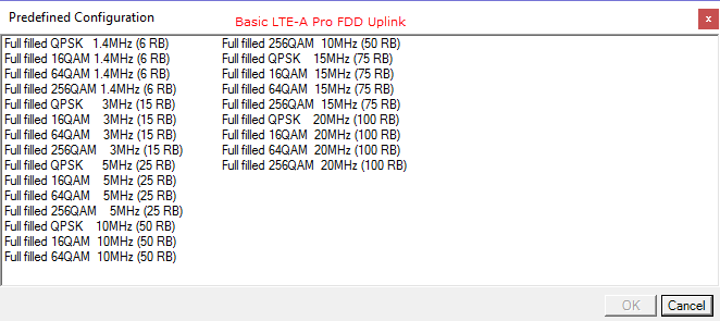
Accesses a ![]() dialog box
from which you can select a base channel configuration.
dialog box
from which you can select a base channel configuration.
Opens the UL RMC Wizard.
Range: 0 to 503
Default: Same as CC index (when Auto Carrier Aggregation Configuration is on), otherwise it is 0
Enter a value for the Cell ID.
The software sets the values in the Physical Layer Cell ID Group and Physical Layer Cell ID Sector cells based on the Cell ID entry. Cell ID = (3 x Physical Cell ID Group) + Physical Cell ID Sector.
See 3GPP TS 36.211 for more information.
Frequency Offset and Cell ID are always editable, even if Auto Carrier Aggregation Configuration is on.
In the case (1) or (2), auto configuration is done for Frequency Offset and Cell ID.
(1) When any action "Add CC" or "Delete CC" or "Copy CC" or Change System BW is done and Auto Carrier Aggregation Configuration parameter is On.
(2) When Auto Carrier Aggregation Configuration parameter is changed to On from Off.
Auto configuration sets Cell ID same as Component Carrier Index.
If Auto Carrier Aggregation Configuration is set to off, auto configuration does not work.
Range: 0 to 65535 (0xFFFF)
Default: 0
Enter a decimal value for the Radio Network Temporary Identifier (RNTI).
Choice: 1.4 MHz (6RB) | 3 MHz (15RB) | 5 MHz (25RB) | 10 MHz (50RB) | 15 MHz (75RB) | 20 MHz (100RB)
Default: 10 MHz (50RB)
Double-click or use the drop-down menu to set the system bandwidth and number of Resource Blocks (RB). When you select a system bandwidth, the software automatically adjusts the value in the cell and the cell.
When the System Bandwidth is decreased, the UL-SCH Tx Sequence window's RB size, and some of the other data channel's settings, are reconfigured, similar to when a Predefined Configuration is executed. But when the System Bandwidth is increased, no change occurs to the UL-SCH Tx Sequence window's RB size or other data channel settings.
The value in this cell is set by the software based on the setting.
The value in this cell is set by the software based on the setting.
Default: 15 kHz
Displays the subcarrier spacing for the uplink. Only the 15 kHz subcarrier spacing is available in this release.
Choice: Normal | Extended
Default: Normal
Double-click or use the drop-down menu to select a or cyclic prefix. The software sets the based on the cyclic prefix selection.
Default: 12
Displays the number of consecutive subcarriers in the uplink resource block.
Default: 7 for Cyclic Prefix; 6 for Cyclic Prefix
Displays the number of consecutive symbols in the uplink resource block. The software sets the based on the selection.
Choice: Off | On
Default: On
Double-click or use the drop-down menu to turn PUSCH DFT Swap on or off.
PUSCH DFT Swap influences how data is mapped to resource elements in the physical uplink shared channel after discrete Fourier transform is performed. PUSCH DFT Swap can be turned on or off to provide two different interpretations of how data should be mapped to resource elements in PUSCH channels. For details about this feature, contact your Keysight representative.
Choice: Off | Group Hopping | Sequence Hopping
Default: Off
Set one or both of the following parameters to to allow manual control of :
Double-click or use the drop-down menu to select or or to turn hopping .
See 3GPP TS36.211 for more information about Group Hopping and Sequence Hopping.
Click this cell and then the  button to open the Configure PUSCH Auto-calculate
window where you can set PUSCH Common parameters.
button to open the Configure PUSCH Auto-calculate
window where you can set PUSCH Common parameters.
Displays the state for automatic calculation of per-slot parameters. To change the displayed state, refer to Set PUSCH Auto-calculate per slot params above.
Displays the value for PUSCH nDMRS(1). This value is used to calculate the Cyclic Shift Alpha (see 3GPP TS36.211). To change the displayed value, refer to Set PUSCH Auto-calculate per slot params above.
Displays the value for PUSCH nDMRS(2). This value is used to calculate the Cyclic Shift Alpha (see 3GPP TS36.211). To change the displayed value, refer to Set PUSCH Auto-calculate per slot params above.
Displays the value for PUSCH Delta SS. This value is used to calculate the sequence-shift pattern (see 3GPP TS36.211). To change the displayed value, refer to Set PUSCH Auto-calculate per slot params above.
Displays the state for PUSCH Frequency Hopping. To change the displayed state, refer to Set PUSCH Auto-calculate per slot params above.
Displays the PUSCH frequency hopping mode (see 3GPP TS36.211).
Displays the PUSCH frequency hopping type (see 3GPP TS36.211).
Displays the PUSCH Frequency Hopping Offset value (see 3GPP TS36.211).
Displays the number of sub-bands (Nsb) (see 3GPP TS36.211).
Displays the value for CURRENT_TX_NB mod 2 (see 3GPP TS36.211).
Click this cell and then the
button to open the Configure
PUCCH Auto-calculate window where you can set PUCCH Common parameters,
including Cyclic Prefix.
Displays the state for automatic calculation of per-slot parameters. To change the displayed state, refer to Set PUCCH Auto-calculate per slot params above.
Displays one of the values used for generating and mapping PUCCH (see 3GPP TS36.211). To change the displayed value, refer to Set PUCCH Auto-calculate per slot params above.
Displays one of the values used for generating and mapping PUCCH (see 3GPP TS 36.211). To change the displayed value, refer to Set PUCCH Auto-calculate per slot params above.
Displays the value of nPUCCH(1) which is used for generating and mapping PUCCH (see 3GPP TS36.211).
This parameter is valid only when PUCCH Auto-calculate per-slot params is set to on.
To change the displayed value, refer to Set PUCCH Auto-calculate per slot params above.
Displays the value of nPUCCH(2) which is used for generating and mapping PUCCH (see 3GPP TS36.211).
This parameter is valid only when PUCCH Auto-calculate per-slot params is set to on.
To change the displayed value, refer to Set PUCCH Auto-calculate per slot params above.
Displays the value of nPUCCH(3) which is used for generating and mapping PUCCH Format 3/3 Short for each subframe (see 3GPP TS36.211).
This parameter is valid only when PUCCH Auto-calculate per-slot params is set to on.
To change the displayed value, refer to Set PUCCH Auto-calculate per slot params above.
Displays one of the values used for generating and mapping PUCCH (see 3GPP TS36.211).
This parameter is valid only when PUCCH Auto-calculate per-slot params is set to on.
To change the displayed value, refer to Set PUCCH Auto-calculate per slot params above.
Choice: Off | On
Default: Off
Double-click or use the drop-down menu to turn the sounding reference signal on or off.
Range: -60 to 20 dB
Default: 0.000 dB
Set the power of the sounding reference signal in dB.
Choice: Off | On
Default: On
Double-click or use the drop-down menu to turn the auto-subframe configuration on or off.
Range: 0 to 14
Default: 0
Enter a value for the sounding reference signal subframe configuration (see 3GPP TS 36.211). Auto-Subframe Configuration must be set to on for this parameter to be active.
Range: 0 to 9
Default: 0
Enter the number of individual subframes separated by commas (example: 0,1,2,3) or a range of subframes (example: 0-3) to assign the sounding reference signal to specific subframes. Auto-Subframe Configuration must be set to off for this parameter to be active.
Range: 0 to 7
Default: 0
Enter a real number value for the sounding reference signal cyclic shift (nSRS_CS). See 3GPP TS 36.211.
Range: 0 to 7
Default: 7
Enter a value for the sounding reference signal bandwidth configuration (C_SRS). See 3GPP TS 36.211.
Range: 0 to 3
Default: 0
Enter a value for the sounding reference signal bandwidth (B_SRS). See 3GPP TS 36.211.
SRS Bandwidth (B_SRS), SRS Hopping Bandwidth (b_hop), and Frequency Hopping are related as follows:
Range: 0 to 1
Default: 0
Enter a value for the sounding reference signal transmission comb (kTC). See 3GPP TS 36.211.
Range: 0 to 3
Default: 0
Enter a value for the sounding reference signal hopping bandwidth (b_hop). See 3GPP TS 36.211.
SRS Bandwidth (B_SRS), SRS Hopping Bandwidth (b_hop) and Frequency Hopping are related as follows:
Range: 0 to 23
Default: 0
Enter a value for the sounding reference signal frequency domain position (nRRC). See 3GPP TS 36.211.
Range: 0 to 636
Default: 0
Enter a value for the sounding reference signal configuration index (I_SRS). See 3GPP TS 36.211.
Displays the SRS periodicity and subframe offset. These values are set by the software and are in accordance with 3GPP TS 36.213 V8.5.0 Table 8.2-1.
Displays the frequency hopping state (read only), which is automatically set by below rule. See 3GPP TS 36.211.
SRS Bandwidth (B_SRS), SRS Hopping Bandwidth (b_hop), and Frequency Hopping are related as follows:
Refer to Resource Mapping Graph for detailed information.