Additional downlink Setup parameters are described in Cell Specific Reference Signal (Basic LTE FDD Downlink), Synchronization Signals (Basic LTE FDD Downlink), and Power Relevant Parameters (Basic LTE FDD Downlink).
|
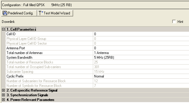
1. Cell Parameters |
|---|
Range: 0 to 503
Default: 1
Enter a value for the Cell ID. The software sets the values in the and cells based on the entry.
Cell ID = [(3 x Physical Cell ID Group) + Physical Cell ID Sector].
See 3GPPTS 36.211.
Range: 0 to 167
Default: 0
The software sets this value based on the entry for the .
Cell ID = [(3 x Physical Cell ID Group) + Physical Cell ID Sector].
See 3GPPTS 36.211.
Choice: 0 | 1 | 2
Default: 0
The software sets this value based on the entry for the .
Cell ID = [(3 x Physical Cell ID Group) + Physical Cell ID Sector].
See 3GPPTS 36.211.
Choice: 0 | 1 | 2 | 3
Default: 0
In multi-antenna configurations, specify the antenna to be used for transmitting the downlink signal. The available selections are determined by the setting. The combination of the setting and the setting determines the resource elements that are reserved for reference signals as described in 3GPP TS 36.211.
MIMO pre-coding is not applied in the Basic carrier, use an Advanced carrier for generating a signal with MIMO pre-coding applied.
Choice: 1 Antenna | 2 Antennas | 4 Antennas
Default: 1 Antenna
In multi-antenna configurations, specify the total number of antennas used for downlink transmission. The combination of the setting and the setting determines the resource elements that are reserved for reference signals as described in 3GPP TS36.211.
MIMO pre-coding is not applied in the Basic carrier, use an Advanced carrier for generating a signal with MIMO pre-coding applied.
Choice: 1.4 MHz (6RB) | 3 MHz (15RB) | 5 MHz (25RB) | 10 MHz (50RB) | 15 MHz (75RB) | 20 MHz (100RB)
Default: 5 MHz (25RB)
Double-click or use the drop-down menu to set the system bandwidth and number of Resource Blocks (RB). When you select a system bandwidth, the software automatically adjusts the value in the cell and the cell.
When the System Bandwidth is decreased, the DL-SCH Tx Sequence window's RB size, and some of the other data channel's settings, are reconfigured, similar to when a Predefined Configuration is executed. But, when the System Bandwidth is increased, no change to the DL-SCH Tx Sequence window's RB size, or the other data channel's settings occurs.
The value in this cell is set by the software based on the setting.
The value in this cell is set by the software based on the setting. The center subcarrier is not used for downlink transmission, so the number of transmitted subcarriers is one less than the number of occupied subcarriers.
Default: 15 kHz
Displays the subcarrier spacing for the downlink. Only the 15 kHz subcarrier spacing is supported in this release.
Choice: Normal | Extended
Default: Normal
Double-click or use the drop-down menu to select a or cyclic prefix. The software sets the based on the cyclic prefix selection.
Default: 12
Displays the number of consecutive subcarriers in a downlink resource block.
Default: 7 for Cyclic Prefix; 6 for Cyclic Prefix
Displays the number of consecutive OFDM symbols in a downlink slot. The software sets the Number of Symbols for Resource Block based on the Cyclic Prefix selection.