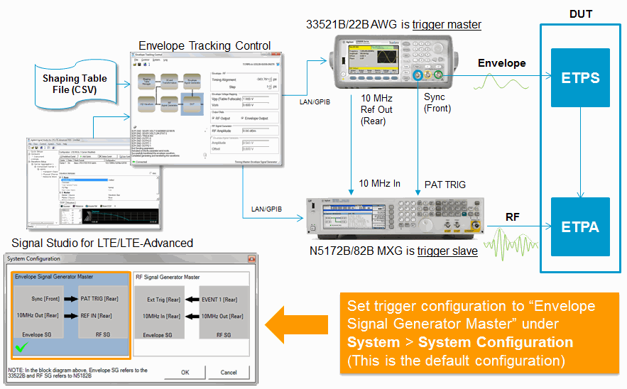
 system overview diagram shows how the Signal Studio's envelope tracking control helps you perform ET testing efficiently.
Envelope tracking (ET) enables you to build, import, and manage multiple shaping tables that can be used to change the power supply voltage levels of a power amplifier (PA), according to the behavior of the RF signal's envelope. This allows you to test PAs for improved battery efficiency and signal quality (i.e. increase output power, reduce distortions, and improve linearity). This  system overview diagram shows how the Signal Studio's envelope tracking control helps you perform ET testing efficiently.
The remaining sections of this topic together provide an example procedure for using Signal Studio's envelope tracking control.
The ET system used in the following example procedure is comprised of the following:
PC running the Signal Studio software
N5172B/82B MXG RF vector signal generator
33521A/22A, 33521B/22B, or 33621A/22A arbitrary waveform generator
Connect the equipment as shown below.
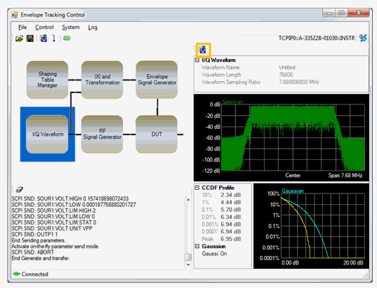
Click the block.
Click the Generate Waveform icon to view spectrum and CCDF curve.
You can skip these steps and generate IQ waveform together with envelope later.
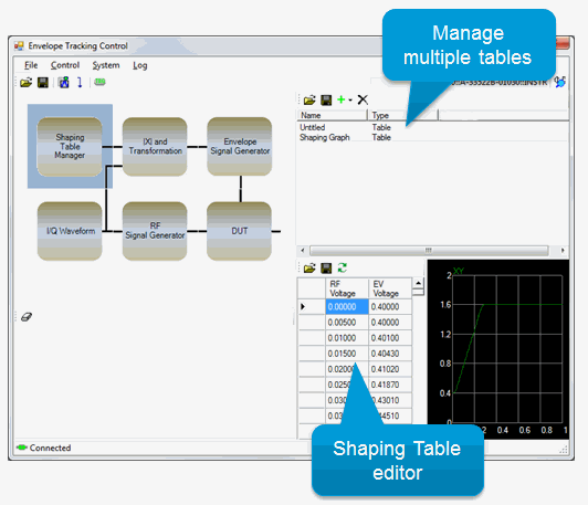
Click the block.
In this window, you can do the following:
Select and apply a shaping table
Create new shaping tables
Assign a unique name to a shaping table
Edit the currently selected shaping table
Import and export shaping tables as CSV files
Make sure you select (highlight) the table you want to apply before going to next step.
Click the block.
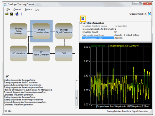
In the parameter view, set the . Higher sample rates produce smoother envelope traces, but use more arbitrary memory space and increase bandwidth.
Click the Generate Envelope Data button.The shaping table you selected in the previous step will now be applied to the generated envelope data.
Compare envelopes before (green) and after (yellow) applying the shaping table. The envelope graph shows only the beginning portion of the entire waveform, so it may not include the largest peak point. Maximum and minimum peak envelope voltage is shown at the top of the graph.
Set the . Choices include the following:
: Use RF output voltage value as conversion table x-axis value. If RF output amplitude is changed, converted data may be changed.
: Use normalized power value of IQ waveform data as conversation table x-axis value. Value range is 0 – 1, so that the 0 – 1 range of x-axis are always used for the conversion. RF output amplitude does not affect the conversion.
: Apply fixed value (not linked to RF output voltage). Fixed value is provided in the parameter.
Set the . This value is used for the rms power level of RF signal for transformation input instead of RF output voltage from RF signal generator amplitude. This parameter appears only when the is set to .
Set the . Applies a band-limiting, low-pass filter (LPF) to the envelope. Bandwidth can be arbitrarily specified from 1 MHz to 200 MHz. The LPF becomes pass-through when the LPF bandwidth is greater than half of the envelope sample clock.
Click the block.
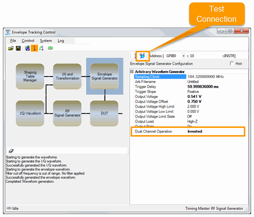
Enter the address for the AWG and click the Check Connection button.
Specify voltage range and limits to protect ETPS input. must be set to for limit settings to work.
Set the impedance: , , or .
For differential operation, select for . Dual channel operation requires a 33522A/B.
Click the block.
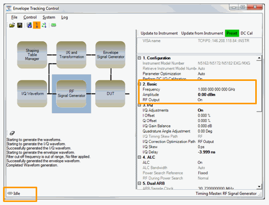
Set RF frequency, amplitude, and other parameters.
Configure trigger settings.
Default setting for is set to .
To Trigger with external trigger input:
Set to
Set to
To Trigger using the button on the RF Signal Generator:
Set to
Set to
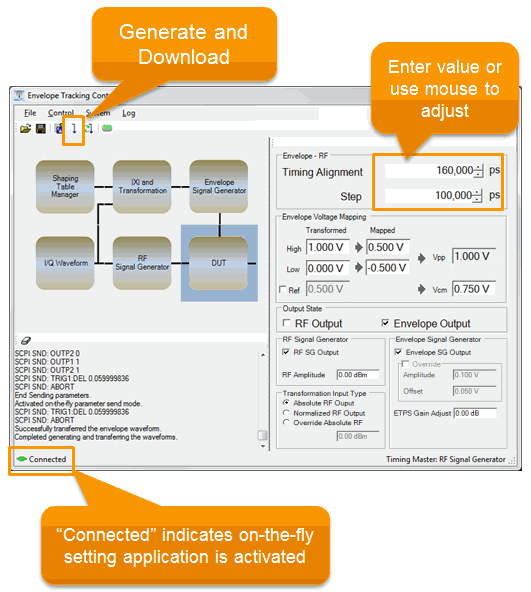
These settings will be applied when you download the IQ waveform and envelope data. Notice that the On-the-Fly indicator in the lower-left corner is set to "Idle." After downloading, the indicator changes to "Connected," allowing you to make real-time changes to these instrument settings.
Click the block.
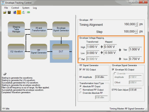
Specify how Vpp and Common Mode Offset voltage (Vcm) corresponds to Shaping Table Y-axis.
Mapped High/Low is mapped to the max value of shaping table Y-axis.
Vcm sets common mode voltage.
As you change RF power, actual voltage swing level will be changed (requires re-generation of envelope).
Actual AWG voltage setting is shown as “Amplitude” and “Offset” in “Envelope Signal Generator.”
See ETPS Input Voltage Mapping for more information.
Press “Generate and Download” button in the toolbar to download IQ and envelope data along with initial configurations.
Notice “Connected” shown in lower left.
Perform timing tuning between IQ and envelope.
Change delay amount and step size.
Timing adjustment setting is applied as you change the value.
