Real Time
PDCCH Transmission Configuration (Advanced LTE FDD Downlink)
In the Channel
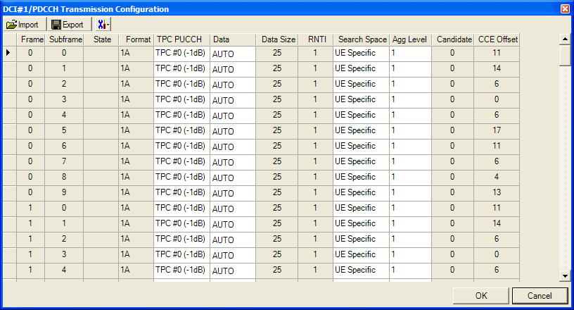
Setup node, select a DCI channel, then click the  button in the Transmission
Configuration cell to open the PDCCH Transmission Configuration dialog
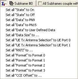
box. Click the Column Preset button
  to access a
  drop-down
list
that enables you to set the parameters for all PDCCH transmissions to
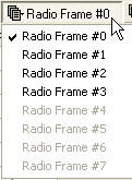
the same value. Click the Radio Frame button
  to access a
  drop-down
list
that enables you to select a radio frame in which to configure the PDCCH.
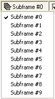
Click the Subframe button
  to access a
  drop-down
list
that enables you to select a subframe in which to configure the PDCCH.
Select the All Subframes couple with subframe #0 checkbox
  to set the parameters for all subframes to the same values as those for
subframe 0.

Frame
Displays radio frame number.
Subframe
Displays subframe number.
State
Choice: On |
Off
Default: Off
Check (On) or clear (Off) to set the channel state.
Format
Displays DCI Format.
TPC PUCCH
Choice: TPC #0 (-1dB)
| TPC #1 (0dB) | TPC #2 (1dB) | TPC #3 (3dB)
Default: TPC #0 (-1dB)
Use the drop-down list to select the TPC PUCCH.
Data
Use the Data
Source Selection dialog box to select , , or to use for the data.
Data Size
Range: 1 to 100
Default: (depends on
DCI Fromat)
Set the number of data bits to use.
RNTI
Range: 0 to 65535 (0xFFFF)
Default: 1 (depends on
DCI #)
Enter a decimal value for the radio network temporary
identifier (RNTI).
Search Space
Choice: Common | UE Specific
Default: UE Specific.
Select a search space from the drop-down list.
Agg Level
Choice: 1 | 2 | 4 | 8
Use the drop-down list to select an aggregation level.
Candidate
This parameter is set by the software.
CCE Offset
The control channel element (CCE) offset is determined
by the CCE aggregation level as follows:
|
1
|
0 | 1 | 2 |... N_PDCCHmax -1
|
|
2
|
0 | 2 | 4 |... N_PDCCHmax -1
|
|
4
|
0 | 4 | 8 |... N_PDCCHmax -1
|
|
8
|
0 | 8 | 16 |... N_PDCCHmax -1
|
 button in the Transmission
Configuration cell to open the PDCCH Transmission Configuration dialog
box. Click the Column Preset button
  to access a
  drop-down
list
that enables you to set the parameters for all PDCCH transmissions to
the same value. Click the Radio Frame button
  to access a
  drop-down
list
that enables you to select a radio frame in which to configure the PDCCH.
Click the Subframe button
  to access a
  drop-down
list
that enables you to select a subframe in which to configure the PDCCH.
Select the All Subframes couple with subframe #0 checkbox
  to set the parameters for all subframes to the same values as those for
subframe 0.


