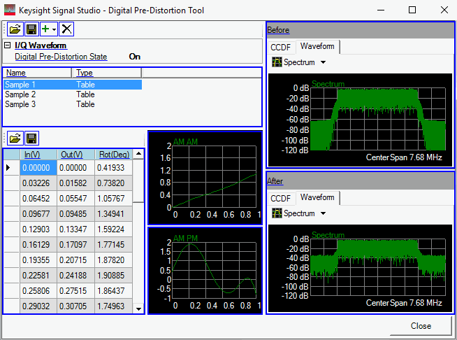
The Digital Pre-Distortion Tool is a modeless window, allowing you access to the main software GUI so you can continue to configure and generate waveforms. Click the various areas in the graphic below for related user interface descriptions.

Opens a window where you can select and import a saved digital pre-distortion settings file (*.dps). The file can contain multiple conversion parameter sets (LUTs).
Opens a window where you can name and save the current digital pre-distortion settings to a file (*.dps). This includes all listed conversion parameter sets (LUTs).
Opens a drop-down menu where you can chose a method for adding a new conversion parameter set (LUTs).
Clears the current lookup table (LUT) so you can manually enter new values for each column.
Opens a window where you can load a comma-separated value file (*.csv) to populate the lookup table (LUT), replacing any pre-existing table. The new table is also added to the list of conversion parameter sets. The order of the values in the file should correspond to the left-to-right order of the columns in the LUT and then repeat. For example: In(V), Out(V), Rot(Deg), and repeat for each row.
This selection is currently not available.
Deletes the selected conversion parameter set (LUT).
Expands the I/Q Waveform property grid.
Sets the digital pre-distortion state to On or Off. Generating a waveform with the state set to On converts the waveform's AM and PM values based on the currently selected lookup table (LUT). You must generate the waveform to see the effect of the LUT values.
This area displays all the conversion parameter sets (LUTs) you have created or imported. Clicking a set immediately populates the LUT values.
This is the file name of the conversion parameter set. You can use this field to rename the file.
This is the type of set. Generally, this is always a table.
This area contains the conversion parameter values for the selected LUT. Values include input voltage, output voltage, and phase rotation. All values can be manually edited by clicking in the table cell.
Opens a window where you can load a comma-separated value file (*.csv) to populate the lookup table (LUT), replacing any pre-existing table. The new table is not added to the list of conversion parameter sets. The order of the values in the file should correspond to the left-to-right order of the columns in the LUT and then repeat. For example: In(V), Out(V), Rot(Deg), and repeat for each row.
Opens a window where you can name and save the current lookup table (LUT) as a comma-separated value file (*.csv).
This column shows the non-distorted input voltage value of each point in the waveform. All values can be manually edited by clicking in the table cell.
This column shows the pre-distorted output voltage value of each point in the waveform. All values can be manually edited by clicking in the table cell.
This column shows the pre-distorted phase rotation in degrees for each point in the waveform. This is in relation to the non-distorted or original waveform. All values can be manually edited by clicking in the table cell.
This graph shows the input voltage (x axis) versus the output voltage (y axis). The graph updates immediately as you select different conversion parameter sets.
This graph shows the input voltage (x axis) versus the phase rotation (y axis). The graph updates immediately as you select different conversion parameter sets.
After generating the waveform, this area displays CCDF and waveform graphs without the digital pre-distortion conversion parameters applied. For more information, refer to Graph View.
After generating the waveform, this area displays CCDF and waveform graphs with the digital pre-distortion conversion parameters applied. For more information, refer to Graph View.