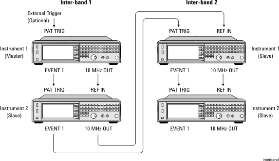
This topic describes how to configure multiple signal generators for an inter-band carrier aggregation test setup. In this example, four signal generators are used to simulate two different RF bands (inter-bands), each with two antennas, to transmit two aggregated component carriers, one in each inter-band.
Any combination of the following Keysight vector signal generators:
N5182B MXG (firmware revision B.01.20 or later)
N5172B EXG (firmware revision B.01.20 or later)
N5182A MXG (all firmware revisions)
PC running N7625C Signal Studio Pro for LTE/LTE-Advanced TDD 2026 software with one of the following options:
Basic LTE-Advanced TDD Release 10
Advanced LTE-Advanced TDD Release 10
LAN connection and cables
BNC cables
Make sure all signal generators are connected to LAN.
Choose one signal generator as the master. This instrument will occupy the Instrument1 position in Inter-band 1. In any configuration, you select only one instrument as the master. All other instruments are considered slaves.
If you are using a combination of N5172B/82B and N5182A models, the master instrument must be an N5172B/82B. Additionally, the N5182A models must occupy the last slave positions in the sequence of instruments. In this configuration, the sequence begins at Inter-band 1, Instrument1 and ends at Inter-band 2, Instrument2. So, if the configuration included two N5182A models, they would need to occupy Instrument1 and Instrument2 of Inter-band 2.
Connect the signal generators as shown in the figure below. For best results, use the shortest BNC cables as possible, while maintaining a uniform length. Optionally, you can connect an external triggering device, such as a function generator, to the PAT TRIG connector of the master signal generator.
This configuration does not require an LO connection for phase coherence.
If you have not already done so, perform an I/Q calibration on each signal generator. On the front panel, press > > Set to > .

Open the N7625C Signal Studio Pro for LTE/LTE-Advanced TDD 2026 software.
In the window that appears, select . Click .
For Step 1 of the System Configuration Wizard, select . Click .
For Step 2, select . Click .
For Step 3, should be selected. Click .
For Step 4, enter the IP addresses for the two instruments in Inter-band 1. You can also test the connections to all in this step. Click .
For Step 5, enter the IP addresses for the two instruments in Inter-band 2. You can also test the connections to all in this step. Click .
Step 6 tests the connections to each signal generator. Click .
For Step 7, enter a name for your hardware configuration that you can recall later. Click .
In the tree view of the software, click the node. The screen that appears is read-only and displays system information, such as instrument models, serial numbers, options, and IP addresses. ![]() View image
View image
Click the or node. Notice that these nodes display the exact same screen as .
For Inter-band 1, click the node. For this example, set the to 2 GHz and to 0 dBm. ![]() View image
View image
For Inter-band 1, click the node. Set the to 2 GHz and to 0 dBm.
For Inter-band 2, click the node. Set the to 800 MHz and to -30 dBm.
For Inter-band 2, click the node. Set the to 800 MHz and to -30 dBm.
Click the node. Notice that you can configure several component carrier parameters, including inter-band assignment. For this example, leave the settings as is. ![]() View image
View image
Click  to generate and download the waveform. This could take several minutes to complete, depending on the complexity of your configuration. A progress bar will appear and you can monitor the messages in the status area of the software interface.
 ![]() View image
View image
During this process, the instrument settings, such as frequency and amplitude, are applied to your system. In addition, the waveform file is downloaded to the instruments and immediately played in accordance with your carrier aggregation settings.
After the waveform is generated, you can also view the CCDF curve for each inter-band by clicking the appropriate tab in the software interface. ![]() View image
View image