 in the Physical Channel node and select PUSCH to open the Configure PUSCH
window.
 Before adding a PUSCH channel as described below, delete any existing transport channel, physical channel, or resource block collection that occupies the resource blocks that your new PUSCH channel will occupy. If you add a new PUSCH channel without first deleting a conflicting channel or resource block collection, a "code conflicted" error occurs when you generate the waveform.
Click the Add Channel button  in the Physical Channel node and select PUSCH to open the Configure PUSCH
window.
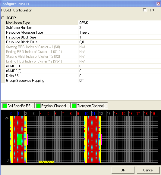
Figure 1 shows the Configure PUSCH window with the default settings.
Links to parameter descriptions are listed in the tables below.

Figure 1. PUSCH default settings
|
|
Select QPSK, 16 QAM, or 64 QAM as the modulation type for the PUSCH.
Range: 0 to 9
Default: 2
Enter a subframe number for the PUSCH.
Range: Type 0 | Type 1
Double-click or use the drop-down menu to select the uplink resource allocation type.
Type 0 : A set of resource blocks continuously allocated by a starting resource block (Resource Block Offset) and length Resource Block Size).
Type 1 : Two sets of resource blocks with each set including one or more consecutive resource block groups of size P where P is the RBG size associated with the system bandwidth. See 3GPP TS 36.213.
Dependency: Resource Allocation Type = Type 0
Enter a value for the number of resource blocks the UL-SCH channel will occupy. The System Bandwidth defined in the UE Setup node determines the range of values for this parameter.
Dependency: Resource Allocation Type = Type 0
Enter an integer offset value for each occupied slot occupied by the UL-SCH, separated by commas. These offsets are applied in order from lowest numbered occupied slot to highest numbered occupied slot.
Range: 1 to 7 (1.4MHz) | 1 to 9 (3MHz ) | 1 to 14 (5MHz) | 1 to 18 (10MHz) | 1 to 20 (15MHz) | 1 to 26 (20MHz)
Default: 1
Dependency: Resource Allocation Type = Type 1
Enter a value for the Starting RBG Index of Cluster #1 (s0) for each subframe respectively, separated by commas (for example, 0,1,0,1...,0,1).The input limitation is s0 < s1 < s2 < s3. See 3GPP TS 36.213.
Range: 1 to 6 (1.4MHz) | 1 to 8 (3MHz ) | 1 to 13 (5MHz) | 1 to 17 (10MHz) | 1 to 19 (15MHz) | 1 to 25 (20MHz)
Default: 1
Dependency: Resource Allocation Type = Type 1
Enter a value for the Starting RBG Index of Cluster #1 (s0) for each subframe respectively, separated by commas (for example, 0,1,0,1...,0,1).The input limitation is s0 < s1 < s2 < s3.See 3GPP TS 36.213.
Range: 1 to 7 (1.4MHz) | 1 to 9 (3MHz ) | 1 to 14 (5MHz) | 1 to 18 (10MHz) | 1 to 20 (15MHz) | 1 to 26 (20MHz)
Default: 1
Dependency: Resource Allocation Type = Type 1
Enter a value for the Starting RBG Index of Cluster #1 (s0) for each subframe respectively, separated by commas (for example, 0,1,0,1...,0,1).The input limitation is s0 < s1 < s2 < s3. See 3GPP TS 36.213.
Range: 1 to 6 (1.4MHz) | 1 to 8 (3MHz ) | 1 to 13 (5MHz) | 1 to 17 (10MHz) | 1 to 19 (15MHz) | 1 to 25 (20MHz)
Default: 1
Dependency: Resource Allocation Type = Type 1
Enter a value for the Starting RBG Index of Cluster #2 (s0) for each subframe respectively, separated by commas (for example, 0,1,0,1...,0,1).The input limitation is s0 < s1 < s2 < s3. See 3GPP TS 36.213.
Choice: 0 | 2 | 3 | 4 | 6 | 8 | 9 | 10
Default: 0
Enter the nDMRS(1) value which is used to calculate the cyclic shift value for the demodulation reference signal (DMRS)
Choice: 0 | 2 | 3 | 4 | 6 | 8 | 9 | 10
Default: 0
Enter the nDMRS(2) value which is used to calculate the cyclic shift value for the demodulation reference signal (DMRS)
Range: 0 to 29
Default: 0
Enter a value which determines the sequence shift pattern for the demodulation reference signal (DMRS) for PUSCH.
Choice: Off | Group Hopping | Sequence Hopping
Default: Off
Double-click or use the drop-down menu to enable the hopping type for the selected transmission.