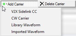
Click this button to open a ![]() drop-down menu
from which you can select a carrier to add to the setup table. The carrier
is inserted above the currently selected row in the table. The maximum
number of carriers is 16.
drop-down menu
from which you can select a carrier to add to the setup table. The carrier
is inserted above the currently selected row in the table. The maximum
number of carriers is 16.
Click this button to delete the currently selected carriers in the setup table. You can highlight multiple carriers for deletion by holding down the CTRL key. You can also use the SHIFT key to select a succession (group) of carriers.
Click this button to quickly add a copy of the selected carrier to the last row in the setup table.
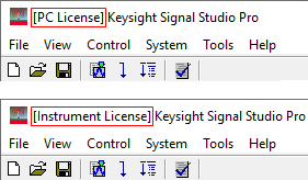
Choices: PC License | Instrument License
Default: PC License.
Double-click or use the drop-down menu to select the playback license mode.
This parameter allows you to switch the waveform playback license mode so you can take advantage of an instrument license, even when a PC license is available.
|
PC License: |
The Waveform Name field is hidden and a fixed name (N7626C: V2X) is assigned to the generated waveform. You cannot change the waveform name. |
|
Instrument License: |
The waveform behavior depends on the licenses installed in the connected instruments. |
When a valid PC license (N7626APPC) exists, this parameter is active, and you can choose either mode.
When a valid PC license does not exist, this parameter is read-only, and Instrument License mode is automatically selected.
The window title shows [PC License] or [Instrument License] to indicate the currently selected license mode. (![]() view image)
view image)
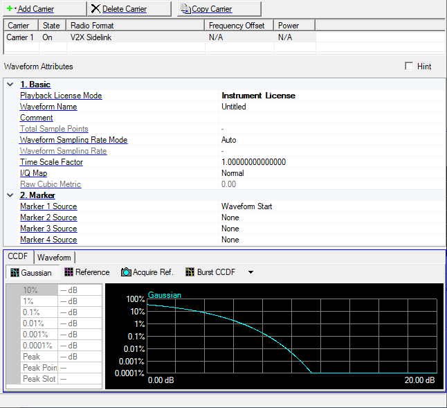
Enter an alpha-numeric waveform file name. The name can include spaces and some special characters: _ $ & # + - [ ].
The maximum name length is 22 characters for non-Windows based instruments (such as E4438C, N5182A and etc), and 150 characters for Windows based instruments. (If you enter a name with more than the maximum name length, the software truncates the name to the length when you click outside of the cell.)
Enter an alpha-numeric comment of up to 32 characters. The comment resides in the file header and can include spaces and special characters.
View the generated waveform length (number of points). You cannot edit this cell.
Waveform length is directly related to the oversampling rate value selected. (Increasing the oversampling rate increases the total sample points.)
Choice: Auto | Manual
Default: Auto
Double-click or use the drop-down menu to select the Sampling Rate Mode.
Auto: Sampling Rate is calculated based on each carriers's settings.
Manual: Uses Waveform Sampling Rate value as a target sampling rate.
Gets or Sets the sampling rate of generated waveform.
This cell is read only.
Waveform Sampling Rate value is calculated based on each carrier settings; Sampling Rate is directly related to the oversampling rate value selected and/or frequency offset value. (Increasing the frequency offset increases the sampling rate.)
After waveform generation has been finished, value is refreshed and up to date.
This cell is editable.
Waveform Sampling Rate value is used as the waveform sampling rate to generate waveform.
Range: (depends on the target instrument.)
Default: (depends on the target instrument, typical 30.72 Msps)
Minimum value is the Least Common Multiple (LCM) value of Base Sampling Rate of carriers or Instrument minimum sampling rate.
Value should be the multiple of LCM value of Base Sampling Rate values within 30.72 Msps.
Minimum value is 1.92 Msps or Instrument minimum sampling rate.
Value should be the multiple of Base Sampling Rate within 30.72 Msps, or the multiple of 30.72 Msps over 30.72 Msps.
Max: 1000
Min: 0.001
Step: 0.00000000000001 (number of decimal places is 14 digits)
Default: 1
Time Scale Factor sets the value by which to scale the bandwidth and time lengths of the measured signal. This setting can be used to compensate for mis-tuned crystals or to allow demodulation of signals at a lower rate, such as half rate or 1/10 rate.
Examples:
For a 1/10 rate signal, the Time Scale Factor would be 0.1.
For a crystal mistuned by 5 ppm, a value of 1.000005 or 0.999995 could be used.
Double-click or use the drop-down menu to select a normal or inverted I/Q signal.
Displays raw cubic metric which can be used for cubic metric (CM) calculation.
This parameter is not available when MIMO hardware configuration is selected.
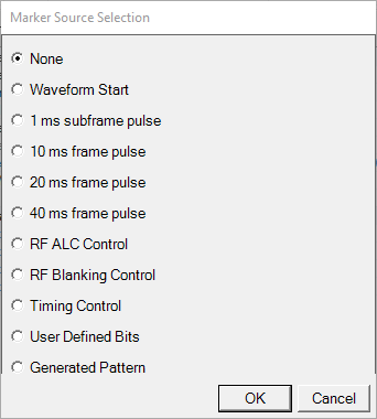
Configure the marker points for marker ![]() dialog box.
dialog box.
The signal generator outputs the marker
Configure the marker points for marker ![]() dialog box.
dialog box.
The signal generator outputs the marker
Configure the marker points for marker ![]() dialog box.
dialog box.
The signal generator outputs the marker
Set Parameter Optimization in the Instrument node to Off to manually set Marker 3 and Marker 4 source, the marker routing, or both.
Configure the marker points for marker ![]() dialog box.
dialog box.
The signal generator outputs the marker
Set Parameter Optimization in the Instrument node to Off to manually set Marker 3 and Marker 4 source, the marker routing, or both.
The graph view displays several different representations of the generated waveform. For more information, see Graph View.