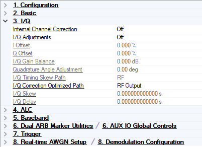
3. I/Q
M9383B VXG-m and M9384B VXG
E8267D PSG
Internal Channel Correction
Choice: On | Off
Default: Off
Double-click or use the drop-down menu to turn the internal channel correction off or on.
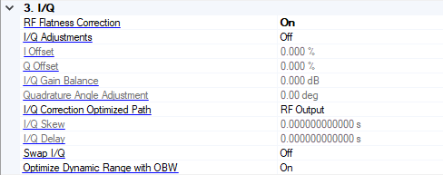
RF Flatness Correction
(M9383B/M9384B only)
Choice: On | Off
Default: On
Double-click or use the drop-down menu to turn the internal channel correction Off or On.
I/Q Adjustments
Choice: Off | On
Default: Off
Double-click or use the drop-down menu to turn the I/Q adjustments On or Off.
On – The values entered for I Offset, Q Offset, and so on are applied to the I and Q signals.
Off – I/Q adjustment values are not applied to the I and Q signals.
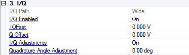
I Offset
Range: -20% to 20 % (-25% to 25% for M9381A)
Step: 0.025%
Default: 0.000%
Enter a DC offset value to apply to the I signal before the I/Q modulator. Use this offset to remove imperfections in the in-phase signal or to introduce calibrated impairments.
When using this setting to minimize the LO feed-through signal, optimum performance is achieved when the adjustment is made after any other I/Q path adjustments. If other adjustments are made after minimization is performed, the LO feed-through signal may increase.
Set I/Q Adjustments to On to enable this parameter.
Q Offset
Range: −20% to 20% (-25% to 25% for M9381A)
Step: 0.025 %
Default: 0.000%
Enter a DC offset value to apply to the Q signal before the I/Q modulator. Use this offset to remove imperfections in the quadrature-phase signal or to introduce calibrated impairments.
When using this setting to minimize the LO feed-through signal, optimum performance is achieved when the adjustment is made after any other I/Q path adjustments. If other adjustments are made after minimization is performed, the LO feed-through signal may increase.
Set I/Q Adjustments to On to enable this parameter.
I/Q Gain Balance
Range: −1 dB to 1 dB
Default: 0.000 dB
Enter a gain ratio, by which I gain exceeds Q gain.
For example, if you enter a value of 1 dB, the I signal will have 1 dB more amplitude than the Q signal. Use the gain balance to remove imperfections in I and Q or introduce calibrated impairments.
Set I/Q Adjustments to On to enable this parameter.
Quadrature Angle Adjustment
Range: -10 to 10 degrees
Default: 0.00 degrees
Enter a value to adjust the Q phase angle. When the quadrature skew is zero, the phase angle between the I and Q vectors is 90 degrees. Positive skew increases the angle from 90 degrees; negative skew decreases the angle from 90 degrees.
Set I/Q Adjustments to On to enable this parameter.
I/Q Timing Skew Path
Choice: RF | BB (Baseband)
Default: RF
Double-click or use the drop-down menu to select the I/Q timing skew path.
Set I/Q Adjustments to On to enable this parameter.
This parameter is not available for all instrument model numbers and may be grayed out.
I/Q Correction Optimization Path
Choice: RF Output | External I/Q Output
Default: RF Output
Double-click or use the drop-down menu to select the I/Q correction optimized path.
-
RF Output − Optimizes the RF OUT path by applying calibration factors to only this path, leaving the I/Q OUT path uncalibrated.
-
External I/Q Output − Optimize the I/Q OUT path by applying calibration factors to only this path, leaving the RF OUT path uncalibrated.
This parameter is not available for all instrument model numbers and may be grayed out.
I/Q Skew
Range: -500 ns to 500 ns (-250 ns to 250 ns for M9381A)
Default: 0.0 seconds
Sets the time delay between I and Q. A positive value delays the I signal relative to the Q signal, and a negative value delays the Q signal relative to the I signal.
Enter a value to change the absolute phase of both I and Q with respect to triggers and markers. A positive value delays I and Q. This value affects both the external I/Q out signals and the baseband signal modulated on the RF output. This adjustment cannot be used with constant envelope modulation and does not affect external I/Q inputs.
Set I/Q Adjustments to On to enable this parameter.
I/Q Delay
Range: -250 ns to 250 ns
Default: 0.0 seconds
Enter a value to set the I/Q delay with respect to triggers and markers.
Set I/Q Adjustments to On to enable this feature.
Swap I/Q
(M9383B/M9384B only)
Choice: On | Off
Default: Off
Double-click or use the drop-down menu to enable or disable the inverse phase rotation of the IQ signal by swapping the I and Q inputs.
Optimize Dynamic Range with OBW
(M9383B/M9384B only)
Choice: On | Off
Default: On
Filters the system RF flatness correction coefficients over the instantaneous bandwidth indicated in the waveform header (or in the “Occupied Bandwidth” settings area under the Signal block when Waveform File is the Vector Modulation Signal Mode). This has the potential to improve EVM performance by not having to correct for flatness errors outside the requested bandwidth.
I/Q Path
(E8267D PSG only)
Choices: Wide
Default: Wide
Gets or sets the External analog I/Q inputs mode.
Wide: Using the Wideband external I/Q inputs, up to 2 GHz RF modulation bandwidth is now easily realized.
I/Q Enabled
(E8267D PSG only)
Choices: On | Off
Default: On
Double-click or use the drop-down menu to control the signal generator's I/Q state.