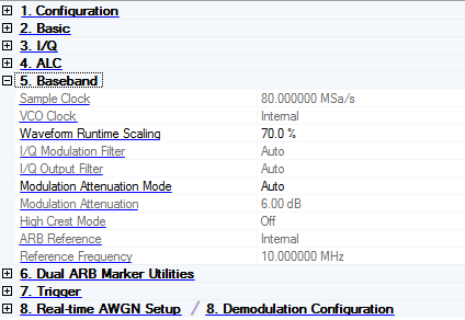
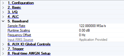
5. Baseband
Capability set to Waveform Playback and Phase Compensation set to Auto, Manual, or Off
Capability set to Real-time Uplink or Phase Compensation set to Auto (Real-time) or Manual (Real-time)
M9420A/M9421A VXT and M9410A/M9411A/M9415A VXT
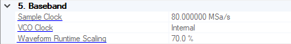
Sample Clock
The sample clock frequency of the signal generator is automatically calculated by the program. The range depends on the connected instrument.
VCO Clock
Choice: Internal | External
Default: Internal
Double-click or use the drop-down menu to select the signal generator’s VCO Clock.
Internal - the signal generator uses its internal VCO Clock.
External - the signal generator uses an external VCO Clock
This parameter is not available for all instrument model numbers and may be grayed out.
Waveform Runtime Scaling
Range: 1 to 100% (100% = no scaling)
Default: 85%
Enter a scaling value for the signal generator to apply to the waveform while it is playing. Use scaling to get the best dynamic range without overflowing the I and Q digital-to-analog converters (DAC) and to reduce the overshoot associated with the DAC interpolation filter. Waveform Runtime Scaling does not change the data in the waveform file.
I/Q Modulation Filter
Choice: Auto | 2.1 MHz | 40 MHz | Through
Default: Auto
Double-click or use the drop-down menu to select a filter for I/Q signals modulated onto the RF carrier. The bandwidth of the baseband signal should dictate the minimum reconstruction filter bandwidth you choose. Depending on the oversampling ratio and where the image frequencies appear, you may want to select a wider bandwidth.
-
Auto − automatically selects a digital modulation filter
-
2.1 MHz − applies a 2.1 MHz baseband filter to the I/Q signals
-
40 MHz − applies a 40 MHz baseband filter to the I/Q signals
-
Through − bypasses filtering
This parameter is not available for all instrument model numbers and may be grayed out.
I/Q Output Filter
Choice: Auto | 40 MHz | Through
Default: Auto
Double-click or use the drop-down menu to select a filter or through path for routing I and Q signals to the rear panel I/Q outputs.
-
Auto − automatically selects an I/Q output filter
-
40 MHz − applies a 40 MHz baseband filter
-
Through − bypasses filtering
This parameter is not available for all instrument model numbers and may be grayed out.
Modulation Attenuation Mode
Choice: Auto | Manual
Default: Auto
Select the mode of the internal I/Q modulator.
-
Manual − manually set the attenuation level of the I/Q modulator using the Modulation Attenuation cell.
-
Auto − the attenuation level automatically sets to a value for best performance based on the digital modulation settings.
Modulation Attenuation
Range: 0.0 to 50.0 dB, the limits depend on the instrument types and options
Default: 6.0 dB
Use this parameter to reduce the signal level driving the I/Q modulation block. Adjusting the attenuation may reduce signal distortion and improve the overall dynamic range.
Set the Modulation Attenuation Mode to Manual to enable this parameter.
High Crest Mode
Choice: Off | On
Default: Off
Double-click or use the drop-down menu to enable or disable the signal generator's high crest mode.
On – processes high-crest-factor arbitrary I/Q waveforms with less distortion. For crest factors higher than 4 dB, you should reduce I/Q Modulation Attenuation levels by 1 dB for each dB above that level. High crest mode reduces the maximum output level and degrades power level accuracy.
Off – disables the high crest mode.
This parameter is not available for all instrument model numbers and may be grayed out.
ARB Reference
Choice: Internal | External
Default: Internal
Double-click or use the drop-down menu to select the signal generator’s ARB reference source.
Internal – the signal generator uses its internally generated 10 MHz signal as the reference source.
External – the signal generator uses an external signal as the reference frequency for the baseband I/Q signal. See the signal generator’s user’s guide for information on external references.
This parameter is not available for all instrument model numbers and may be grayed out.
Reference Frequency
Range: 0.250 to 100 MHz
Default: 10 MHz
Enter a frequency value when using an externally supplied reference signal. See the signal generator user’s guide for information on external references.
Set ARB Reference to External to enable this parameter.
This parameter is not available for all instrument model numbers and may be grayed out.
Sample Rate
Sample Rate displays and sets the rate at which the signal is played from the baseband generator.
Runtime Scaling
Runtime Scaling adjusts the scaling of the I and Q data. Reducing the runtime scaling prevents the over ranges from happening. Runtime scaling is also used to scale signals relative to each other.
Frequency Offset
Frequency Offset moves the baseband signal above or below the carrier by the specified frequency. When simulating adjacent channel interferers, this allows you to offset the waveforms to avoid overlap between the waveforms.
Input RMS Source
RMS Source identifies where the instrument gets the RMS voltage value of the signal to ensure the correct amplitude of the signal is at the output of the signal generator when the power calibration is performed.