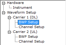
BWP Setup Downlink
Bandwidth part (BWP) is a UE-specific setting, but the N7631C Signal Studio Pro for 5G NR 2021 software does not have a concept of UE. Therefore, separate BWP setup nodes (see below) are required so that each data channel can select which BWP to use.
BWP Setup Node
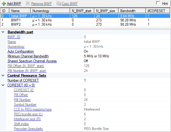
Initial BWP Properties
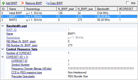
BWP1 (and greater) Properties
Add BWP
Click the Add BWP button  to add a BWP to the setup table. The BWP is inserted above the currently selected BWP in the table. The maximum number of supported BWPs is eight.
Remove BWP
Click the Remove BWP button  to delete the currently selected BWP from the setup table.
Initial BWP in downlink cannot be removed.
Copy BWP
Click the Copy BWP button  to copy the currently selected BWP to the last row of the setup table. The maximum number of supported BWPs is eight.
Bandwidth part
BWP_ID
Display the ID of current BWP, it is automatically generated based on the index of BWP array.
Name
Set the name of the BWP, it will be used as a selection for data channel to select BWP.
Numerology
Choices: u = 0: 15 kHz | u = 1: 30 kHz | u = 2: 60 kHz Normal CP | u = 2: 60 kHz Extended CP for FR1; u = 2: 60 kHz Normal CP | u = 2: 60 kHz Extended CP | u = 3: 120 kHz | u = 4: 240 kHz for FR2.
Default: u = 1: 30 kHz
Display the numerology for the BWP, it is automatically coupled with the numerology under carrier node. This parameter is read-only.
Auto Configuration
Choices: On | Off
Default: On
Set whether Initial BWP is configured automatically by CORESET0 which is related to the RMSI-scs and RMSI-PDCCH-Config in MIB under SSPBCH setting.
If Auto Configuration is set to off, user can input the RB Offset and RB Number of InitialBWP manually, but the InitialBWP should contains CORESET0.
Minimum Channel Bandwidth
Choices: 5 MHz or 10 MHz | 40 MHz
Default: 5 MHz or 10 MHz
Select the minimum channel bandwidth when getting the location and size of the CORESET0 from pdcch-ConfigSIB1 in MIB.
Shared Spectrum Channel Access
Choices: On | Off
Default: Off
Sets the state of shared spectrum channel access. When enabled, the CORESET0 is determined by Table 13-1A/13-4A of 38.213, chapter 13.
RB Offset (N_BWP_start)
Range: N_grid_start to (N_grid_start + N_grid_size - 1)
Default: 0
Set the RB offset of the BWP relative to CRB0.
RB Number (N_BWP_size)
Range: 1 to (N_grid_start + N_grid_size - N_BWP_start)
Default: 273
Set the RB number of the BWP.
Control Resource Sets
Number of CORESET
Range: 1 to 3
Default: 1
Set the number of CORESET of the BWP. A maximum of 3 CORESETs are allowed for each BWP. When this parameter is changed, there are individual CORESET settings that need to be specified for each CORESET.
CORESET (ID = n)
CORESET ID
Range: 0 to 11.
Default: 0
Set the CORESET ID.
1. For Downlink, the CORESET ID 0 is releated to the RMSI-PDCCH-Config in MIB, and can't be used for other CORESETs
2. The CORESET ID is unique in current BWP.
RB Offset
Range: -1 to 5 for non-zero CORESET.
Default: 0 for CORESET0; -1 for others.
For CORESET0: Display the RB Offset of the CORESET0 relative to the start of InitialBWP.
For other CORESET: Set the RB Offset of the first group of 6 RBs relative to the start of BWP, -1 means not configured.
RB Number
Display the RB Number of the CORESET0 which is determined by RMSI-PDCCH-Config in MIB.
Symbol Number
Range: 1 to 3
Default: 1
Set the number of symbols of the CORESET. A maximum of 3 symbols are allowed.
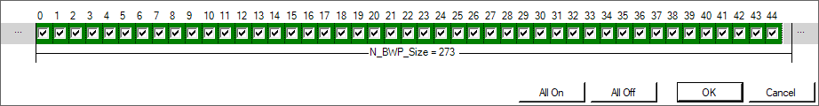
Frequency Domain Bitmap
Displays the  frequency domain bitmap editor of CORESET. This parameter is used to represent the CORESET frequency location in RRC signaling and specify the RB allocation of CORESET.
CCE to REG mapping type
Choices: Non-Interleaved | Interleaved
Default: Non-Interleaved
Select the CCE to REG mapping type of CORESET.
REG bundle size (L)
Choices: 2 | 6 for N_symb_CORESET = 1; N_symb_CORESET | 6 for N_symb_CORESET = 2 or 3
Default: 6
Set the REG bundle size (L) of CORESET for interleaved CCE to REG mapping.
Interleaver size (R)
Choices: 2 | 3 | 6
Default: 2
Set the Inter leaver size (R) of CORESET for interleaved CCE to REG mapping.
Shift index
Range: 0 to 274
Default: 0
Set the shift index of CORESET for non-initial BWP when CCE to REG mapping is interleaved.
The shift index is equal to cell ID for Initial BWP, i.e. CORESET0.
Precoder Granularity
Choices: REG Bundle Size | CORESET Size
Default: REG Bundle Size
Set the Precoder Granularity of the CORESET.