Downlink Channel Setup
The downlink carrier includes the following channels:
SS/PBCH
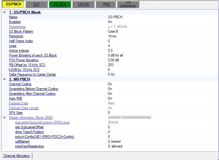
1. SS/PBCH Block
Name
Set the name for the channel. The channel name is used for DCI/DL-SCH/UCI/UL-SCH Configurations.
Enabled
Enable or disable the channel or signal in a radio frame.
Numerology
For Single Numerology mode, this parameter is read-only and automatically coupled with the numerology under carrier node. For Multiple Numerologies mode, this parameter is editable, the choices are based on the FR1 or FR2.
SS Block Pattern
Select the SS Block Pattern, it is automatically coupled for subcarrier spacing 15k/120/240 cases, and it is selectable for subcarrier spacing 30k case.
Periodicity
Choices: 5ms | 10ms | 20ms | 40ms | 80ms | 160ms
Default: 5ms
Select the SSB periodicity.
Half Frame Index
Range: 0 to 1
Default: 0
Set the SSB location to the first half frame or the second half frame when SSB period is not 5ms.
Lmax
Choices: 4 | 8 for u=0 and u=1; 64 for u=3 and u=4
Default: 4
Select the Lmax of SSB.
Active Indices
Set the active indices of the SSB. There are 3 ways to configure:
-
To configure by individual index, use ',' as the delimiter, e.g. 0,1,2,3.
-
To configure by a range of index, use ':' to indicate the start index and the last index, e.g. 3:10 means 3,4,5,6,7,8,9,10.
-
To configure by a certain step, use two ':' to indicate the start index, the step and the last index, e.g. 0:4:12 means 0, 4, 8, 12.
These 3 configuration methods can be used in combination, by using ',' as the delimiter, e.g. 0,1,4:7,8:2:19 means index 0,1,4,5,6,7,8,10,12,14,16,18.
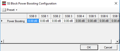
Power Boosting of each SS Block
Range: -40 to 40dB
Default: 0dB
Bring up the power boosting editor to set the power boosting for each active SS Block. SS/PBCH does not have a single value of power boosting, instead, there is a table to set the power boosting for each SS block. The value of non-active SS Blocks are grayed out
PSS Power Boosting
Range: -40 to 40dB
Default: 0dB
Set the PSS power boosting relative to SSS or PBCH.
RB Offset by 15kHz SCS
Set the RB offset of SSB relative to CRB0, it is expressed in terms of 15kHz for µ=0 and µ=1, and 60kHz for µ=3 and µ=4.
To avoid some unclear case, some limitation for k0:
-
For the case of 30kHz SSB, k0 can only be an even number.
-
For the case of 120kHz SSB, k0 can only be an even number.
-
For the case of 240kHz SSB, k0 can only be multiple of 4.
The range is based on the max RB and numerology of the carrier.
When the numerology of carrier is changed, RB Offset and k0 are automatically updated to ensure the SSB is in the middle of carrier for the new numerology.
kSSB by 15kHz SCS
Range: 0 to 23 for u=0 and u=1; 0 to 11 for u=3 and u=4.
Default: 0
Set the kSSB for SS/PBCH. For the case of 30kHz or 120kHz SSB, kSSB can only be an even number, for the case of 240kHz SSB, kSSB can only be multiple of 4.
When the numerology of carrier is changed, RB Offset and k0 are automatically updated to ensure the SSB is in the middle of carrier for the new numerology.
Delta Frequency of Carrier Center
Set the relative location of SS/PBCH center in Hz directly compared to the CC center, and it will be coupled with RB Offset and kSSB in two-way.
2. NR-PBCH
Channel Coding
Choices: On | Off
Default: On
Enable or disable transport layer channel coding.
Scrambling Before Channel Coding
Choices: On | Off
Default: On
Enable or disable the scrambling before channel coding for PBCH.
Scrambling After Channel Coding
Choices: On | Off
Default: On
Enable or disable the scrambling after channel coding for PBCH.
Auto MIB
Choices: On | Off
Default: On
Set whether MIB is generated automatically, when enabled, the contents under Master Information Block will be included in the payload data. If it is set to Off, Payload Data is editable and you can set PBCH contents manually.
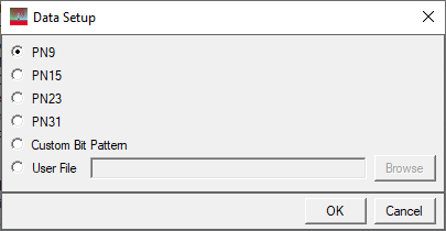
Payload Data
Choices: PN9 | PN15 | PN23 | PN31 | Custom Bit Pattern | User File
Default: PN9
Brings up the  Data Setup payload editor to select the data bits used for the channel payload.
Payload Data Length
Display the MIB length before channel coding.
SFN Start
Range: 0 to 1023
Default: 0
Set the SFN for the first generated frame, the SFN will be increased for multiple frames case.
Master Information Block (MIB)
Display the SS/PBCH payload bits when Auto MIB is enabled, it is generated by the MIB contents of each fields, and all the unlisted fields of MIB are set to 0.
subcarrierSpacingCommon (RMSI-scs)
Choices: 15,000 | 30,000 for FR1; 60,000 | 1,20,000 for FR2.
Default: 30,000
Set the subcarrierSpacingCommon value in MIB content, it is read-only for Single Numerology mode.
ssb-SubcarrierOffset
Range: 0 to 31
Default: 0
This parameter corresponds to kSSB. When kSSB changes, it will be equal to kSSB, but you can manually modify it to a value larger than 23.
The 4 least significant bits of kSSB are in the MIB contents, and the most significant bit of kSSB is in the PBCH payload.
dmrs-TypeA-position
Choices: 2 | 3.
Default: 2
Set the value of dmrs-TypeA-position in MIB content.
pdcch-ConfigSIB1 (RMSI-PDCCH-Config)
Range: 0 to 255
Default: 0
Set the value of pdcch-ConfigSIB1 (RMSI-PDCCH-Config) in MIB content, which is used to determine the location of Initial downlink BWP, see more information in section 13 of 38.213.
cellBarred
Choices: 0: barred | 1: notBarred
Default: 0: barred
Set the value of cellBarred in MIB content.
intraFreqReselection
Choices: 0: allowed | 1: notAllowed
Default: 0: allowed
Set the value of intraFreqReselection in MIB content.
DCI
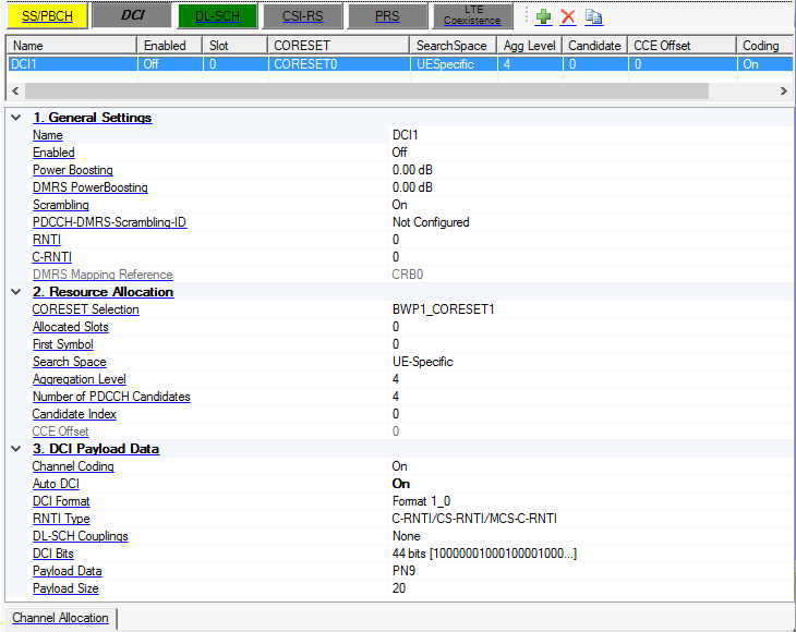
1. General Settings
Name
Set the name for the channel. The channel name is used for DCI/DL-SCH/UCI/UL-SCH Configurations.
Enabled
Enable or disable the channel or signal in a radio frame.
Power Boosting
Range: -40 to 40dB
Default: 0dB
Set the additional power boosting for the channel.
DMRS PowerBoosting
Range: -40 to 40dB
Default: 0dB
Set the DMRS power boosting relative to data part.
Scrambling
Enable or disable the scrambling for the channel.
PDCCH-DMRS-Scrambling-ID
Range: -1 to 65535
Default: Not Configured.
Set the PDCCH-DMRS-Scrambling-ID for sequence generation, enter -1 means Not Configured.
RNTI
Set the RNTI for the channel.
C-RNTI
Range: 0 to 65535
Default: 0
Set the C-RNTI for a PDCCH, used for the following:
-
Scrambling in UE-specific search space if the pdcch-DMRS-ScramblingID is configured
-
CCE offset calculation in UE-specific search space if it is not 0
DMRS Mapping Reference
Display the DMRS mapping reference of DCI, CORESET0 is selected if DCI is transmitted in CORESET0, otherwise CRB0 is selected, see section 7.4.1.3.2 of TS38.211 for more information.
2. Resource Allocation
-
Time domain: Use Allocated Slots to set slot allocation, and the symbol allocation is determined by the CORESET selection.
-
Frequency domain: Select BWP first, and then CORESET index in the BWP. After selecting CORESET index, use CCE offset and CCE number to set the frequency location of DCI.
CORESET Selection
Choices: All the CORESETS in all the BWPs
Default: BWP1_CORESET1
Select the CORESET to be used for DCI transmission.
Allocated Slots
Set the allocated slot index for the channel. There are 3 ways to configure:
-
To configure by individual index, use ',' as the delimiter, e.g. 0,1,2,3.
-
To configure by a range of index, use ':' to indicate the start index and the last index, e.g. 3:10 means 3,4,5,6,7,8,9,10.
-
To configure by a certain step, use two ':' to indicate the start index, the step and the last index, e.g. 0:4:12 means 0, 4, 8, 12.
These 3 configuration methods can be used in combination, by using ',' as the delimiter, e.g. 0,1,4:7,8:2:19 means index 0,1,4,5,6,7,8,10,12,14,16,18.
First Symbol
Default: 0
Display the first symbol index for the DCI transmission, the symbol number of DCI is defined in selected CORESET.
Search Space
Choices: UE-Specific | Common
Default: UE-Specific
Select the search space type of current PDCCH.
Aggregation Level
Choices: 1 | 2 | 4 | 8 | 16
Default: 4
Set aggregation level for current PDCCH.
Number of PDCCH Candidates
Choices: 1 | 2 | 3 | 4 | 5 | 6 | 8
Default: 4
Set the number of PDCCH candidates to calculate the CCE Offset.
Candidate Index
Range: -1 to Number of PDCCH Candidates - 1.
Default: 0
Set candidate index of the search space which the PDCCH is located.
CCE Offset
Set the CCE offset indicating where DCI starts from.
The range is based on the selected CORESET settings. For UE-specific search space and if RNTI is not 0, the CCE Offset is different for each slot with each value corresponding to one slot. If Candidate Index is set to -1, you can input CCE Offset manually, but only one value is accepted.
3. DCI Payload Data
Channel Coding
Choices: On | Off
Default: On
Enable or disable transport layer channel coding.
Auto DCI
Choices: On | Off
Default: Off
Enable or disable Auto DCI, when enabled, you can edit each fields for DCI contents.
DCI Format
Choices: Format 0_0 | Format 0_1 | Format 1_0 | Format 1_1
Default: Format 1_0
Select the DCI format.
RNTI Type
Choices: based on the selected DCI format.
Default: C-RNTI/CS-RNTI/new-RNTI
Select the RNTI Type.
DL-SCH Couplings
Choices: based on the DL-SCH list
Default: None
Set which DL-SCH is coupled with current DCI.
If DCI is coupled with a DL-SCH, after any changes on the DL-SCH side, scheduling information will be automatically filled into DCI field, and RNTI, allocated slots and BWP selection are also coupled with DL-SCH.
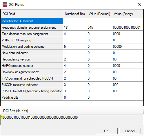
DCI Bits
Displays the number of DCI bits. Click  to open the DCI Fields editor to set each field of DCI, based on the selected DCI format and RNTI type.
Payload Data
Choices: PN9 | PN15 | PN23 | PN31 | Custom Bit Pattern | User File
Default: PN9
Brings up the Data Setup payload editor to select the data bits used for the channel payload.
Payload Size
Range: 1 to (CCE Number * 108 - 24)
Default: 20
Set the DCI payload size before channel coding.
DL-SCH
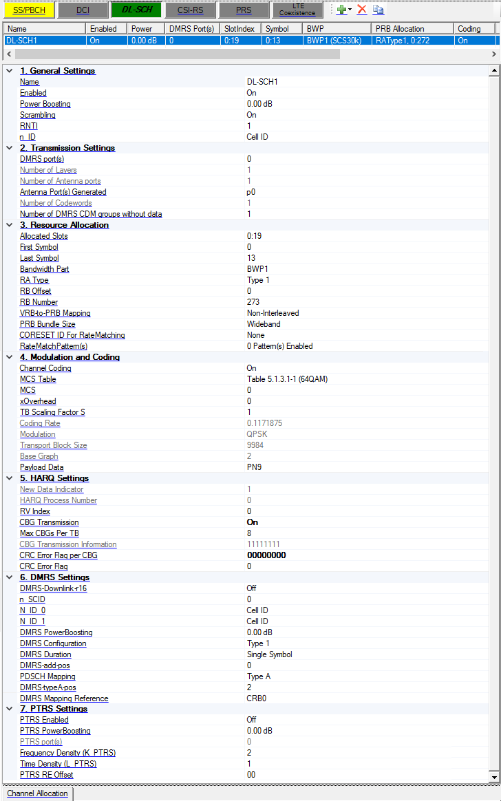
1. General Settings
Name
Set the name for the channel. The channel name is used for DCI/DL-SCH/UCI/UL-SCH Configurations.
Enabled
Enable or disable the channel or signal in a radio frame.
Power Boosting
Range: -40 to 40dB
Default: 0dB
Set the additional power boosting for the channel.
Scrambling
Choices: On | Off
Default: On
Enable or disable the scrambling for the channel.
RNTI
Range: 0 to 65535
Default: 0
Set the RNTI for the channel.
n_ID
Range: -1 to 1023
Default: Cell ID
Set the n_ID for sequence generation, -1 means cell ID.
2. Transmission Settings
DMRS port(s)
Set the DMRS port(s) used for the transmission of this channel, multiple values input are allowed, such as 0,1,2,3, or 0:3, the Number of layers is automatically coupled with the number of DMRS ports.
Number of Layers
Default: 1
Display the number of layers for DL-SCH, it is automatically coupled with the DMRS port(s).
Number of Antenna Ports
Display the number of Antenna Ports used for transmission, it is automatically coupled with the Antenna Port Set.
Antenna Port Generated
Use this drop-down menu to choose the desired option.
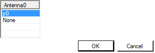
Enter a comma-separated string or click drop down arrow to set the mapping between physical antennas and logical antenna ports, the number of physical antennas is under Waveform Setup node.
Number of Codewords
Only one codeword is supported, so the maximum number of antenna ports is 4.
Number of DMRS CDM groups without data
Set the number of DMRS CDM groups without data, which is used to determine how many resource elements are reserved for DMRS. When this parameter changes, the DMRS power boosting is automatically coupled based on the table 4.1-1 of 38.214.
3. Resource Allocation
-
Time domain: Use Allocated Slots to set slot allocation, and the symbol allocation is determined by the CORESET selection.
-
Frequency domain: Select BWP first, and then CORESET index in the BWP. After selecting CORESET index, use CCE offset and CCE number to set the frequency location of DCI.
Allocated Slots
Range: 0 to number of slots in a frame for current numerology -1
Set the allocated slot index for the channel. There are 3 ways to configure:
-
To configure by individual index, use ',' as the delimiter, e.g. 0,1,2,3.
-
To configure by a range of index, use ':' to indicate the start index and the last index, e.g. 3:10 means 3,4,5,6,7,8,9,10.
-
To configure by a certain step, use two ':' to indicate the start index, the step and the last index, e.g. 0:4:12 means 0, 4, 8, 12.
These 3 configuration methods can be used in combination, by using ',' as the delimiter, e.g. 0,1,4:7,8:2:19 means index 0,1,4,5,6,7,8,10,12,14,16,18.
First Symbol
Range: 0 to 13 for Normal CP; 0 to 11 for Extended CP
Default: 0
Set the first symbol index for the transmission.
Last Symbol
Range: FirstSymbol to 13 for Normal CP; FirstSymbol to 11 for Extended CP.
Default: 13
Set the last symbol index for the transmission.
Bandwidth Part
Select a bandwidth part to be used for transmission, all the BWP names defined under BWP Setup node will be list here.
RA Type
Choices: Type0 | Type1
Default: Type1
Set the resource allocation type for the transmission.
RB Offset
Choices: Type0 | Type1
Default: Type1
Set the RB offset relative to selected BWP, it is used for RA Type1.
RB Number
Range: 1 to RB Number of BWP - RB Offset
Default: 273
Set the RB number used for transmission, it is used for RA Type1.
VRB-to-PRB Mapping
Choices: Non-Interleaved | Interleaved
Default: Non-Interleaved.
Coupling: Read-only for RA Type 0
Select the VRB to PRB mapping type.
PRB Bundle Size
Choices: 2 | 4 | Wideband
Default: Wideband
Set the PRB Bundle Size of DL-SCH.
CORESET ID For RateMatching
Choices: All the CORESET ID of current BWP will be listed here
Default: None
Select the CORESET ID of current BWP for DL-SCH rate matching.
RateMatchPattern(s)
Click the button to pen the Rate Match Pattern editor to set the rate match patterns.
Although RateMatchPattern is a cell level or BWP level settings, the RateMatchPatterns defined under each DL-SCHs are only applied to current DL-SCH.
4. Modulation and Coding
Channel Coding
Choices: On | Off
Default: On
Enable or disable transport layer channel coding.
MCS Table
Choices: Table 5.1.3.1-1 | Table 5.1.3.1-2
Default: Table 5.1.3.1-1
Select which table to use for the TB size calculation.
MCS
Range: 0 to 27 or 28
Default: 0
Set MCS index for the channel.
xOverhead
Choices: 0 | 6 | 12 | 18
Default: 0
Set the xOverhead parameter (N_oh_PRB) to calculate to TB size.
TB Scaling Factor S
Choices: 1 | 0.5 | 0.25
Default: 1
Set the TB Scaling Factor (S) to calculate to TB size.
Coding Rate
Display the coding rate of the channel. It is automatically updated by MCS index change.
Modulation
Default: QPSK
Display the modulation type of the channel. It is automatically updated by MCS index change.
Transport Block Size
Display the transport block size of the channel. It is automatically updated by MCS index change and is calculated based on the MCS Index and the formula in 5.1.3 of 38.214.
The Xoh-PDSCH parameter is assumed to 0.
Base Graph
Display the base graph of the channel. It is automatically updated by MCS index change.
Payload Data
Choices: PN9 | PN15 | PN23 | PN31 | Custom Bit Pattern | User File
Default: PN9
Brings up the Data Setup payload editor to select the data bits used for the channel payload.
5. HARQ Settings
New Data Indicator
Default: 0
Sets the New Data Indicator for this DL-SCH. Enter -1 means that the New Data Indicator is auto generated based on the HARQ Process Number.
Example: If there are 10 slots for a DL-SCH, and New Data Indicator set to -1, and the HARQ Process Number set to 0:3, then the HARQ ID for these 10 slots will be 0,1,2,3,0,1,2,3,0,1; and the NDI for these 10 slots will be 0,0,0,0,1,1,1,1,0,0.
HARQ Process Number
Default: 0
Sets the HARQ Process Number used for the transmission of this channel. Multiple values input are allowed, such as 0,1,2,3, or 0:3, then they are applied to different slots.
Example: If there are 10 slots for a DL-SCH, and New Data Indicator set to -1, and the HARQ Process Number set to 0:3, then the HARQ ID for these 10 slots will be 0,1,2,3,0,1,2,3,0,1; and the NDI for these 10 slots will be 0,0,0,0,1,1,1,1,0,0.
RV index
Range: 0 to 3
Default: 0
Set the RV Index.
CBG Transmission
Default: Off
Enable or disable CBG transmission.
Max CBGs Per TB
Choices: 2 | 4 | 6 | 8
Default: 8
Set the maxCodeBlockGroupsPerTransportBlock when CBG transmission is enabled.
CBG Transmission Information
Default: 11111111
Enter an one-zero string to set the CBG ransmission information for re-transmission with CBG transmission enabled, the length of string is MaxCBGsPerTB.
CRC Error Flag per CBG
Default: 00000000
Enter an one-zero string to set the whether CRC error is inserted for current TB or CBG. For CBG transmission enabled, the length of string is MaxCBGsPerTB, for CBG transmission disabled, the length of string is 1.
CRC Error Flag
Default: 00000000
Enter an one-zero string to set the whether CRC error is inserted for current TB or CBG. For CBG transmission enabled, the length of string is MaxCBGsPerTB, for CBG transmission disabled, the length of string is 1.
6. DMRS Settings
DMRS-Downlink-r16
Choices: On | Off
Default: Off
Set whether higher-layer parameter DMRS-Downlink-r16 is provided.
n_SCID
Range: 0 to 1
Default: 0
Set the n_SCID for sequence generation.
N_ID_0
Range: -1 to 65535
Default: Cell ID
Set the N_ID_nSCID (N_ID_0 or N_ID_1) for sequence generation, enter -1 means cell ID.
N_ID_1
Range: -1 to 65535
Default: Cell ID
Set the N_ID_nSCID (N_ID_0 or N_ID_1) for sequence generation, enter -1 means cell ID.
DMRS Power Boosting
Range: -40 to 40dB
Default: 0dB
Set the DMRS power boosting relative to data part.
When the number of DMRS CDM groups without data is changed, the DMRS power boosting is automatically changed based on the Table 4.1-1 of 38.214.
DMRS Configuration
Choices: Type 1 | Type 2
Default: Type 1
Set the DMRS Configuration for the channel.
DMRS Duration
Choices: Single Symbol | Double Symbol
Default: Single Symbol
Set the DMRS Duration for the channel.
DMRS-add-pos
Default: 0
Set the DMRS-add-pos for the channel.
The range is based on the Symbol Number, DMRS Duration, Mapping Type and DMRS-typeA-pos.
PDSCH Mapping
Choices: Type A | Type B
Default: Type A
Set the PDSCH Mapping type for the channel.
DMRS-typeA-pos
Choice: 2 | 3 | MIB.
Default: 2
Set the DMRS-typeA-pos for the channel. It will be automatically coupled to the MIB contents under SS/PBCH if MIB is selected.
When DL-SCH is overlapped with SS/PBCH (either active SSB or non-active SSB), any RB partial or fully occupied by SS/PBCH is not used for DL-SCH transmission for all the symbols.
DMRS Mapping Reference
Choices: CRB0 | CORESET0
Default: CRB0
Set the DMRS mapping reference of DL-SCH, see section 7.4.1.1.2 of TS38.211 for more information.
7. PTRS Settings
PTRS Enabled
Choices: On | Off
Default: Off
Enable or disable PTRS signal generation.
PTRS Power Boosting
Range: -40 to 40dB
Default: 0dB
Set the PTRS power boosting relative to data part.
PTRS port(s)
For downlink, because there is only one codeword supported, the PTRS port is associated with the lowest indexed DMRS port among the DMRS port(s), so this parameter is read-only, and always equal to the minimum DMRS port.
If the PTRS port is larger than 3 for DMRS configuration type1 or larger than 5 for DMRS configuration type2, this is an invalid case, so the PTRS is forced to off and set to read-only.
Frequency Density (K_PTRS)
Choices: 2 | 4
Default: 2
Set the Frequency Density (K_PTRS) for PTRS signal.
Time Density (L_PTRS)
Choices: 1 | 2 | 4
Default: 1
Set the Time Density (L_PTRS) for PTRS signal.
PTRS RE Offset
Choices: 00 | 01 | 10 | 11
Default: 00
Select the PTRS RE Offset for PTRS signal generation.
CSI-RS
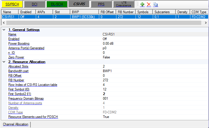
1. General Settings
Name
Set the name for the channel.
Enabled
Enable or disable the channel or signal in a radio frame.
Power Boosting
Range: -40 to 40dB
Default: 0dB
Set the additional power boosting for the channel.
Antenna Port(s) Generated
Enter a comma-separated string or click drop down arrow to set the mapping between physical antennas and logical antenna ports, the number of physical antennas is under Waveform Setup node.
n_ID
Range: 0 to 65535
Default: 0
Set the n_ID for CSI-RS sequence generation.
Zero Power
Choices: True | False
Default: False
Set whether CSI-RS is Zero-power of non-zero-power.
2. Resource Allocation
-
Time domain: Use Allocated Slots to set slot allocation, and the symbol allocation is determined by the CORESET selection.
-
Frequency domain: Select BWP first, and then CORESET index in the BWP. After selecting CORESET index, use CCE offset and CCE number to set the frequency location of DCI.
Allocated Slots
Set the allocated slot index for the channel. There are 3 ways to configure:
-
To configure by individual index, use ',' as the delimiter, e.g. 0,1,2,3.
-
To configure by a range of index, use ':' to indicate the start index and the last index, e.g. 3:10 means 3,4,5,6,7,8,9,10.
-
To configure by a certain step, use two ':' to indicate the start index, the step and the last index, e.g. 0:4:12 means 0, 4, 8, 12.
These 3 configuration methods can be used in combination, by using ',' as the delimiter, e.g. 0,1,4:7,8:2:19 means index 0,1,4,5,6,7,8,10,12,14,16,18.
Bandwidth part
Select a bandwidth part to be used for transmission, all the BWP names defined under BWP Setup node will be list here.
RB Offset
Range: 0 to (RB Offset of BWP + RB Number of BWP - 4)
Default: 0
Set the RB offset relative to CRB0, corresponding to higher layer parameter startingRB, it should be multiple of 4.
RB Number
Range: 4 to RB Number of BWP
Default: 272
Set the RB number used for CSI-RS, corresponding to higher layer parameter nrofRBs, it should be multiple of 4.
Row Index of CSI-RS Location table
Range: 0 to 18
Default: 4
Set the row index of CSI-RS location table (table 7.4.1.5.3-1 in 38.211).
First Symbol (l0)
Range: 0 to 13 but may be limited according to the number of l' in the CSI-RS table.
Default: 12
Set the first symbol index (l0) of CSI-RS.
First Symbol2 (l1)
Range: 2 to 12 but may be limited according to the number of l' in the CSI-RS table.
Default: 12
Set the first symbol index2 (l1) of CSI-RS.
Frequency Domain Bitmap
Set the CSI-RS frequency-domain location using bitmap, the length of bitmap is related to Row Index.
Number of Antenna Ports
Default: 4
Display the number of Antenna Ports used for CSI-RS, it is automatically coupled with Row Index.
Density
Set the Density of CSI-RS, the choices are updated by Row Index of CSI-RS Location Table.
PRB Allocation for Density = 0.
Choices: Even PRBs | Odd PRBs
Default: Even PRBs
Select Even or Odd PRBs used for CSI-RS when Density is 0.5.
CDM Type
Display the CDM Type of CSI-RS, it is automatically updated by Row Index of CSI-RS Location Table.
Resource Elements used for PDSCH
Choices: True | False
Default: True
Sets whether the resource elements assigned to CSI-RS can be used for PDSCH if CSI-RS collides with PDSCH. If true, PDSCH will be mapped to the resource element and CSI-RS will overwrite the values. If false, PDSCH will not be mapped to the resource elements.
PRS
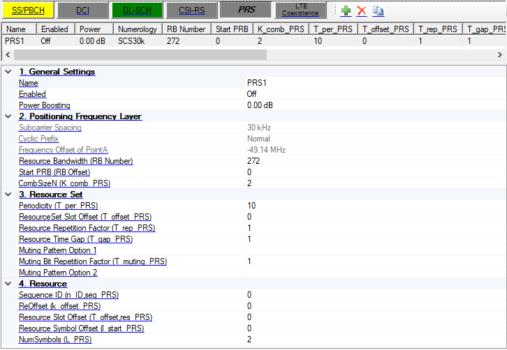
1. General Settings
Name
Set the name for the channel.
Enabled
Enable or disable the channel or signal in a radio frame.
Power Boosting
Range: -40 dB to 40 dB
Default: 0 dB
Set the additional power boosting for the channel.
2. Positioning Frequency Layer
Subcarrier Spacing
Choices:
Single Numerology mode: Same as Subcarrier Spacing of Carrier.
Multiple Numerology mode: 15 kHz | 30 kHz | 60 kHz for FR1, 60 kHz | 120 kHz for FR2.
Default: 30 kHz
Select the Subcarrier Spacing for PRS.
For single numerology mode, the Subcarrier Spacing is fixed to the Subcarrier Spacing of carrier. There will be an error if Subcarrier Spacing of carrier is 240 kHz.
For multiple numerology mode, the Subcarrier Spacing selections are 15 kHz, 30 kHz, 60 kHz for FR1, 60 kHz, and 120 kHz for FR2. If the corresponding resource grid is not enabled, there will be an error.
Cyclic Prefix
Choices: Normal | Extended for 60 kHz Subcarrier Spacing; Fixed to Normal otherwise.
Default: Normal
Select the Cyclic Prefix for PRS.
For single numerology mode, the Cyclic Prefix is fixed to the Cyclic Prefix of carrier.
For multiple numerology and 60 kHz Subcarrier Spacing is selected, Cyclic Prefix is selectable, otherwise it is fixed to Normal.
Frequency Offset of PointA
Display the relative location of Point A (in Hz) for PRS from the middle of the carrier. Currently only the case that PointA of PRS is same as PointA of Carrier is supported.
Resource Bandwidth (RB_Number)
Range: 24 to 272 (granularity is 4).
Default: 272
Set the Resource Bandwidth for PRS in RB number.
Although the range for Resource Bandwidth is 1 to 63, defined in 37.355, which is one-to-one mapping to 24 to 272 RBs, the software uses the RB Number directly for convenience.
The RB Number should less than the resource grid size of selected mu. If the resource grid size is less than 24, there will be an error.
The RB Number should be less than the resource grid size of selected numerology.
Start PRB (RB_Offset)
Range: Should ensure that all the RBs of PRS are in the range of selected resource grid.
Default: 0
Set the Start PRB for PRS.
CombSizeN (K_comb_PRS)
Choices: 2 | 4 | 6 | 12
Default: 2
Select the CombSizeN (K_comb_PRS) for PRS.
3. Resource Set
Periodicity (T_per_PRS)
Choices: 2^mu * (4 | 5 | 8 | 10 | 16 | 20 | 32 | 40 | 64 | 80 | 160 | 320 | 640 | 1280 | 2560 | 5120 | 10240)
Default: 10
Select the Periodicity (T_per_PRS) for PRS.
ResourceSet Slot Offset (T offset PRS)
Range: 0 ~ (Periodicity - 1)
Default: 0
Set the ResourceSet Slot Offset (T_offset_PRS) for PRS.
Resource Repetition Factor (T_rep_PRS)
Choices: 1 | 2 | 4 | 6 | 8 | 16 | 32
Default: 1
Select the Resource Repetition Factor (T_rep_PRS) for PRS.
Resource Time Gap (T_gap_PRS)
Choices: 1 | 2 | 4 | 8 | 16 | 32
Default: 1
Select the Resource Time Gap (T_gap_PRS) for PRS.
Muting Pattern Option 1
The length of this bitmap (L) could be 0 | 2 | 4 | 8 | 16 | 32.
Default: Empty
Enter an one-zero string to set the Muting Pattern for option 1.
Muting Bit Repetition Factor (T_muting_PRS)
Choices: 1 | 2 | 4 | 8
Default: 1
Select the Muting Bit Repetition Factor (T_muting_PRS) for PRS.
Muting Pattern Option 2
The length of this bitmap should be 0 or equal to Resource Repetition Factor.
Default: Empty
Enter an one-zero string to set the Muting Pattern for option 2.
4. Resource
Sequence ID (n_ID.seg_PRS)
Range: 0 to 4095
Default: 0
Set the Sequence Id (n_ID,seq_PRS) for PRS.
ReOffset (k_offset_PRS)
Range: 0 to (combSizeN - 1)
Default: 0
Set the ReOffset (k_offset_PRS) for PRS.
Resource Slot Offset (T_offset.res_PRS)
Range: 0 to min(511, (Periodicity - ResourceSetSlotOffset - 1))
Default: 0
Set the Resource Slot Offset (T_offset,res_PRS) for PRS.
Resource Symbol Offset (I_start_PRS)
Range: 0 to 12 for Normal CP; 0 to 10 for Extended CP.
Default: 0
Set the Resource Symbol Offset (l_offset_PRS) for PRS.
Num Symbols (L_PRS)
Choices: 2 | 4 | 6 | 12 (Should ensure allocated symbols are all in the slot).
Default: 2
Set the Number of symbols (L_PRS) for PRS.
LTE Coexistence
This property grid sets the parameters for LTE.
For single numerology case, LTE coexistence can only be enabled when the numerology is 15 kHz. For multi-numerology case, LTE coexistence can only be enabled when the 15 kHz resource grid is enabled. Otherwise, there will be an error message at the bottom of GUI, and an error icon on the LTE coexistence button, as shown below.

When LTE-CRS conflicts with other channels, the behaviors are as described in the table below.
|
LTE-CRS |
SS/PBCH |
Not Allowed |
|
LTE-CRS |
DCI |
Not Allowed |
|
LTE-CRS |
DL-SCH |
Rate Matching |
|
LTE-CRS |
DMRS of DL-SCH |
Should be illegal case, send DMRS |
|
LTE-CRS |
PTRS of DL-SCH |
Should be illegal case, send PTRS |
|
LTE-CRS |
CSI-RS |
Yes, but should on the different subcarriers |
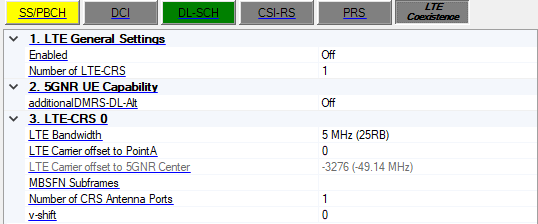
1. LTE General Settings
Enabled
Enable or disable LTE coexistence. When enabled, the resource elements for LTE-CRS are reserved and not available for PDSCH. It can only be enabled for 15 kHz numerology.
Number of LTE-CRS
Range: 1 to 4
Default: 1
Set the number of LTE-CRS, when it changes, the number of LTE-CRS will be changed on GUI with different category.
2. 5GNR UE Capability
additionalDMRS-DL-Alt
Choices: On | Off
Default: On
Indicates whether the 5GNR UE supports the alternative additional DMRS position for co-existence with LTE CRS.
3. LTE-CRS 0
LTE Bandwidth
Choices: 1.4 MHz (6RB) | 3 MHz (15RB) | 5 MHz (25RB) | 10 MHz (50RB) | 15 MHz (75RB) | 20 MHz (100RB)
Default: 5 MHz (25RB)
Sets the LTE bandwidth.
LTE Carrier offset to PointA
Range: 0 to 16383
Default: 0
Set the LTE carrier center subcarrier location determined by offset from point A using 15k subcarrier spacing.
LTE Carrier offset to 5GNR Center
Displays the LTE carrier center subcarrier location determined by offset from 5GNR carrier center using the number of 15k subcarrier spacing and frequency offset value in brackets.
MBSFN Subframes
Range: 0 to 9
Sets the subframe index, which is to be configured as MBSFN subframes in LTE. Default is empty means no subframe for MBSFN. There are 3 ways to configure:
To configure by individual index, use ',' as the delimiter, e.g. 0,1,2,3.
To configure by a range of index, use ':' to indicate the start index and the last index, e.g. 3:5 means 3,4,5.
To configure by a certain step, use two ':' to indicate the start index, the step and the last index, e.g. 0:2:6 means 0, 2, 4, 6.
Number of CRS Antenna Ports
Choices: 1 | 2 | 4
Default: 1
Set the number of antenna ports for LTE-CRS.
v-shift
Range: 0 to 5
Default: 0
Sets the v-shift value for LTE-CRS. It is given by LTE Cell ID mod 6.