Uplink Channel Setup
The uplink carrier consists of the following channels:
UCI
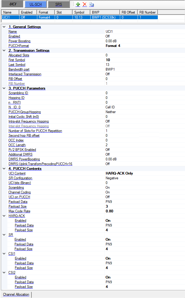
All the PUCCH formats are supported. The table below provides a summary of the parameters list for each PUCCH format.
-
Bold means new parameters.
-
Yellow means only visible for non-interlaced transmission.
-
Blue means only visible for interlaced transmission.
|
Parameter |
Format0 |
Format1 |
Format2 |
Format3 |
Format4 |
R16 Update |
|---|---|---|---|---|---|---|
|
Allocated slots |
● |
● |
● |
● |
● |
|
|
First Symbol |
● |
● |
● |
● |
● |
|
|
Last Symbol |
● |
● |
● |
● |
● |
|
|
Bandwidth part |
● |
● |
● |
● |
● |
|
|
Interlaced transmission |
● |
● |
● |
● |
● (read only to off) |
New parameter. Interlaced transmission is not applicable for PUCCH format4. Interlaced transmission is set to off and read-only for mu 2/3/4. |
|
RB Offset |
● |
● |
● |
● |
● |
Only visible when Interlaced transmission is off. |
|
RB Number |
● 1 (read only) |
● 1 (read only) |
● 1~16 |
● 1,2,3,4,5,6,8,9,10,12,15,16 |
● 1 (read only) |
|
|
RB set index |
● |
● |
● |
● |
|
New parameter. Only visible when Interlaced transmission is on. Interlace1 can't be same as Interlace0. |
|
Interlace0 |
● |
● |
● |
● |
|
|
|
Interlace1 |
|
|
● |
● |
|
|
|
PUCCH-Group Hopping |
● |
● |
|
● |
● |
|
|
Initial Cyclic shift (m0) |
● |
● |
|
|
|
|
|
Hopping ID |
● |
● |
|
● |
● |
|
|
Scrambling ID |
|
|
● |
● |
● |
|
|
n_RNTI |
|
|
● |
● |
● |
|
|
N_ID_0 |
|
|
● 0~65535, -1 means Cell ID. |
● 0~65535, -1 means Cell ID. |
● 0~65535, -1 means Cell ID. |
For PUCCH F3/F4, Only visible when DMRSuplinkTransformPrecodingPUCCH-r16 is on. |
|
Intra-slot Frequency Hopping |
● (Set to off and read-only for one symbol case) |
● |
● (Set to off and read-only for one symbol case) |
● |
● |
Only visible when Interlaced transmission is off. Second hop PRB is visible when intra-slot frequency hopping or inter-slot frequency hopping is enabled. |
|
Second hop PRB |
● |
● |
● |
● |
● |
|
|
Inter-slot Frequency Hopping |
|
● (can be set when more than 1 slots are allocated) |
|
● (read only to off) |
● (read only to off) |
|
|
Number of slots for PUCCH repetition |
|
● |
|
● |
● |
|
|
SR Configuration |
● |
|
|
|
|
|
|
OCC Index |
|
● The range is based on the table 6.3.2.4.1-1/2 of 38.211 |
● The range is 0 to OCC Length - 1 |
● The range is 0 to OCC Length - 1 |
● The range is 0 to OCC Length - 1 |
For PUCCH F2/F3, Only visible when Interlaced transmission is on. |
|
OCC Length |
|
|
● (1 or 2 or 4) |
● (1 or 2 or 4) |
● (2 or 4) |
|
|
Pi/2BPSK Enabled |
|
|
|
● |
● |
|
|
Additional DMRS |
|
|
|
● |
● |
|
|
DMRS power boosting |
|
● |
|
● |
● |
|
|
DMRSuplinkTransformPrecodingPUCCH-r16 |
|
|
|
● |
● |
New parameter. |
|
UCI Bits (Binary) |
Old parameter, now change to use payload data and payload size. |
|
|
|
|
|
|
UCI Bits per slot |
● (Display the UCI bits per slot based on the payload data and payload size) |
|
|
|
|
|
|
Scrambling |
|
|
● |
● |
● |
|
|
Channel Coding |
|
|
● |
● |
● |
|
|
Payload Data |
● |
● |
● |
● |
● |
|
|
Payload Size |
● or 2 |
● 1 or 2 |
● |
● |
● |
|
Couplings for interlaced transmission:
-
The intra-cell guard band setting is used to determine the number/location of RB-sets, and the RB-set index should be one of the RB-sets. if the selected RB-set is less than 100RB (for mu0) or 50RB (for mu1), there will be an error.
-
The BWP used for PUCCH should contains the selected RB-set, otherwise there will be an error.
-
It is clear that Intra-slot frequency hopping is not used for interlaced transmission, but not clear about Inter-slot frequency hopping, I assume it is also not used for interlaced transmission.
-
For interlace1, -1 means 'not configured'.
The conflict check between multiple UCIs is removed.
1. General Settings
Name
Sets the name for the channel. The channel name is used for DCI/DL-SCH/UCI/UL-SCH Configurations.
Enabled
Enable or disable the channel or signal in a radio frame.
Power Boosting
Range: -40 to 40 dB
Default: 0 dB
Set the additional power boosting for the channel.
PUCCH Format
Choices: Format 0 | Format 1 | Format 2 | Format 3 | Format 4
Default: Format 0
Select the PUCCH format for the transmission.
2. Transmission Settings
Allocated Slots
Range: 0 to number of slots in a frame for current numerology -1
Set the allocated slot index for the channel. There are 3 ways to configure:
-
To configure by individual index, use ',' as the delimiter, e.g. 0,1,2,3.
-
To configure by a range of index, use ':' to indicate the start index and the last index, e.g. 3:10 means 3,4,5,6,7,8,9,10.
-
To configure by a certain step, use two ':' to indicate the start index, the step and the last index, e.g. 0:4:12 means 0, 4, 8, 12.
These 3 configuration methods can be used in combination, by using ',' as the delimiter, e.g. 0,1,4:7,8:2:19 means index 0,1,4,5,6,7,8,10,12,14,16,18.
First Symbol
Range: 0 to 13 for Normal CP; 0 to 11 for Extended CP.
Default: 0
Set the first symbol index for the transmission.
Last Symbol
Range: FirstSymbol to 13 for Normal CP; FirstSymbol to 11 for Extended CP.
Default: 13
Set the last symbol index for the transmission.
Bandwidth part
Select a bandwidth part to be used for transmission, all the BWP names defined under BWP Setup node will be list here.
Interlaced Transmission
Choices: On | Off
Default: Off
Enable or disable Interlaced Transmission.
RB Offset
Range: 0 to RB Number of BWP - 1
Default: 0
Set the RB offset relative to selected BWP, it is used for RA Type1.
RB Number
Range: 1 to RB Number of BWP - RB Offset
Default: 273
Set the RB number used for transmission, it is used for RA Type1.
3. PUCCH Parameters
Scrambling ID
Range: -1 to 65535
Default: Not Configured.
Set the Scrambling-ID for sequence generation, enter -1 means Not Configured.
Hopping ID
Range: 0 to 1023
Default: 0
Set the Hopping ID for PUCCH format 0/1/3/4.
n_RNTI
Range: 0 to 65535
Default: 0
Set the n_RNTI for PUCCH format 2/3/4 sequence generation.
N_ID_0
Range: -1 to 65535
Default: Cell ID
Set the N_ID_0 for PUCCH format 2 DMRS sequence generation, enter -1 means cell ID.
PUCCH-GroupHopping
Choices: Neither | Enabled | Disabled
Default: Neither
Set the PUCCH-GroupHopping for PUCCH format 0/1/3/4 sequence generation.
Initial Cyclic Shift (m0)
Range: 0 to 11
Default: 0
Set the initial cyclic shift (m0) for PUCCH format 0 and format 1.
Intra-slot Frequency Hopping
Choices: On | Off
Default: Off
Enable or disable Intra-slot Frequency Hopping, it is set to off and read-only when the number of symbols is 1 for PUCCH format 0/2. Intra-slot frequency hopping and Inter-slot frequency hopping cannot be enabled at the same time.
Inter-slot Frequency Hopping
Choices: On | Off
Default: Off
Enable or disable Inter-slot Frequency Hopping when the number of allocated slots is larger than 1, only PUCCH format 1 is supported. Intra-slot frequency hopping and Inter-slot frequency hopping cannot be enabled at the same time.
Number of Slots for PUCCH Repetition
Range: 1 ~ Min (The number of allocated slots, 8)
Default: 1
Set the number of slots for repetitions of a PUCCH transmission for PUCCH format 1/3/4.
Second hop RB Offset
Range: 0 to RB Number of BWP - 1
Default: 0
Set the Second hop RB offset when Intra-slot Frequency Hopping is enabled.
OCC Index
For PUCCH format 1: the range is based on the table 6.3.2.4.1-1/2 in 38.211 for PUCCH format1.
For PUCCH format 4: the range is 0 to OCCLength -1.
Default: 0
Set the OCC Index for PUCCH format 1/4 sequence generation.
OCC Length
Choices: 2 | 4
Default: 2
Set the OCC Length for PUCCH format 4 sequence generation.
Pi/2 BPSK Enabled
Choices: On | Off
Default: Off
Enable or disable pi/2 BPSK for PUCCH format 3/4.
Additional DMRS
Choices: On | Off
Default: Off
Set additional DMRS for PUCCH format 3 and format 4.
DMRS PowerBoosting
Range: -40 to 40 dB
Default: 0 dB
Coupling: this parameter appears only for PUCCHFormat Format 2, Format 3, and Format 4
Set the DMRS power boosting relative to data part.
DMRS-UplinkTransformPrecodingPUCCH-r16
Choices: On | Off
Default: Off
Coupling: this parameter appears only for PUCCHFormat Format 3 and Format 4
Set whether higher-layer parameter DMRS-UplinkTransformPrecodingPUCCH-r16 is provided.
4. PUCCH Contents
UCI Content
Choices: SR+HARQ-ACK | HARQ-ACK Only | SR Only
Default: SR+HARQ-ACK
Select UCI content on PUCCH for Format 0/1. SR+HARQ-ACK is only applicable for Format 0.
When UCI Content = SR Only:
-
SR Configuration can only be Positive.
-
Payload Data and Payload Size will not be shown.
-
UCI Bits per slot is NA for format 0, and is 0 for format 1.
When UCI Content = HARQ-ACK Only:
-
SR Configuration will not be shown.
-
Payload Data, Payload Size and UCI Bits per slot are same as before.
When UCI Content = SR + HARQ-ACK:
-
Same as before, and it is only applicable for format 0.
SR Configuration
Choices: Negative | Positive
Default: Negative
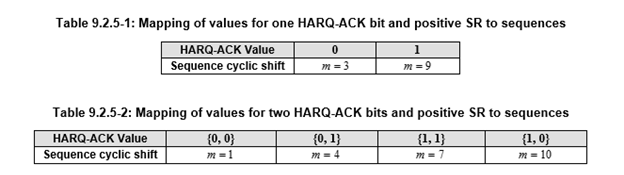
Select the SR Configuration. SR is defined in 9.2 in 38.213. The definition in 9.2.4 UE procedure for reporting SR is not supported.
When SR is positive, tables 9.2.5-1 and 9.2.5-2 are used.
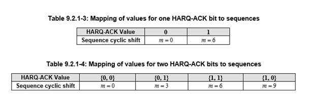
When SR is negative, or UE procedure for reporting HARQ-ARK without SR, tables 9.2.1-3 and 9.2.1-4 are used.
UCI Bits
Displays the UCI bits for each slot of the first generated frame when PUCCH format is format 0 or format 1.
Scrambling
Choices: On | Off
Default: On
Enable or disable the scrambling for the channel.
Channel Coding
Choices: On | Off
Default: On
Enable or disable transport layer channel coding.
UCI on PUCCH
Choices: On | Off
Default: Off
Enable or disable UCI contents on PUCCH for Format 2/3/4. When enabled, HARQ-ACK/SR/CSI1/CSI2 are used as the payload of PUCCH; otherwise, payload data is used.
Payload Data
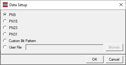
Choices: PN9 | PN15 | PN23 | PN31 | Custom Bit Pattern | User File
Default: PN9
Brings up the  Data Setup payload editor to select the data bits used for the channel payload.
Payload Size
Default:
1 for PUCCH format 0/1
20 for PUCCH format 2/3/4.
Sets the UCI payload size.
For PUCCH format 2/3/4, the payload size is before channel coding, the range is determined by the PUCCH resource allocation, and ensures the coding is working correctly.
For PUCCH format 0/1, the range is 1 to 2.
Max Code Rate
Choices: 0.08 | 0.15 | 0.25 | 0.35 | 0.45 | 0.60 | 0.80
Default: 0.8
Set the PUCCH Max Code Rate.
HARQ-ACK
Set HARQ-ACK on PUCCH.
SR
Set SR on PUCCH.
CSI1
Set CSI1 on PUCCH.
CSI2
Set CSI2 on PUCCH.
Enabled
Enable or disable the channel or signal in a radio frame.
Payload Data
Choices: PN9 | PN15 | PN23 | PN31 | Custom Bit Pattern | User File
Default: PN9
Brings up the Data Setup payload editor to select the data bits used for the channel payload.
Payload Size
Range: 1 ~ 1706 for others.
Default: 4
Set the HARQ-ACK/SR/CSI1/CSI2 payload size before channel coding.
If the resource may not be enough for channel coding, there will be an error.
UL-SCH
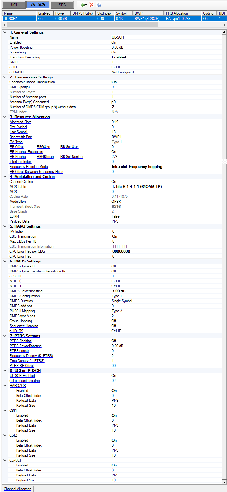
1. General Settings
Name
Sets the name for the channel. The channel name is used for DCI/DL-SCH/UCI/UL-SCH Configurations.
Enabled
Enable or disable the channel or signal in a radio frame.
Power Boosting
Range: -40 to 40 dB
Default: 0 dB
Set the additional power boosting for the channel.
Scrambling
Choices: On | Off
Default: On
Enable or disable the scrambling for the channel.
Transform Precoding
Default: Disabled
Enable or disable Transform Precoding for uplink.
RNTI
Range: 0 to 65535
Default: 0
Set the RNTI for the channel.
n_ID
Range: -1 to 1023
Default: Cell ID
Set the n_ID for sequence generation, enter -1 means cell ID.
n_RAPID
Range: -1 to 63
Default: Not Configured
Set the n_RAPID for sequence generation, enter -1 means Not Configured.
2. Transmission Settings
Codebook-Based Transmission
Default: Off
Enable or disable Codebook-Based Transmission.
The range is based on the Number of Layers and Number of Antenna Ports. When Codebook-Based Transmission is Off, the Number of Layers is same as the Number of Antenna Ports. When Codebook-Based Transmission is On, the Number of Layers can be equal to or smaller than the Number of Antenna Ports. See 6.3.1.5 in 38.211 for more information.
DMRS port(s)
Sets the DMRS port(s) used for the transmission of this channel. Multiple values input are allowed, such as 0,1,2,3, or 0:3. The number of layers is automatically coupled with the number of DMRS ports.
Number of Layers
Default: 1
Display the number of layers for UL-SCH, it is automatically coupled with the DMRS port(s).
Number of Antenna Ports
Choice: 1 | 2 | 4
Default: 1
Set the number of antenna ports for UL-SCH when codebook-based transmission is enabled, it should not be smaller than the Number of Layers.
Antenna Port(s) Generated
Enter a comma-separated string or click drop down arrow to set the mapping between physical antennas and logical antenna ports, the number of physical antennas is under Waveform Setup node.
The logical antenna ports are expressed as p0, p1, ....
Number of DMRS CDM groups without data
Range: 1 to 2 for DMRS configuration type 1; 1 to 3 for DMRS configuration type 2.
Default: 1
Set the number of DMRS CDM groups without data, which is used to determine how many resource elements are reserved for DMRS. When this parameter changed, the DMRS power boosting is automatically coupled based on the table 4.1-1 of 38.214.
TPMI Index
Default: 0
Set the TPMI Index when Codebook-based Transmission is enabled, the range is based on the number of layers and number of antenna ports.
| Number of Layers | Number of Antenna Ports | Valid value for TMPI Index |
|---|---|---|
| 1 | 2 | 0-5 |
| 2 | 2 | 0-2 |
| 1 | 4 | 0-27 |
| 2 | 4 | 0-21 |
| 3 | 4 | 0-6 |
| 4 | 4 | 0-4 |
3. Resource Allocation
-
Time domain: use ‘Allocated Slots’ to set slot allocation, and ‘First symbol’ and ‘Last symbol’ to set the symbol allocation for each slot.
-
Frequency domain: Select BWP first, and then set RB offset and RB number for the selected BWP, only RA Type 1 is supported.
Allocated Slots
Range: 0 to number of slots in a frame for current numerology -1
Set the allocated slot index for the channel. There are 3 ways to configure:
-
To configure by individual index, use ',' as the delimiter, e.g. 0,1,2,3.
-
To configure by a range of index, use ':' to indicate the start index and the last index, e.g. 3:10 means 3,4,5,6,7,8,9,10.
-
To configure by a certain step, use two ':' to indicate the start index, the step and the last index, e.g. 0:4:12 means 0, 4, 8, 12.
These 3 configuration methods can be used in combination, by using ',' as the delimiter, e.g. 0,1,4:7,8:2:19 means index 0,1,4,5,6,7,8,10,12,14,16,18.
First Symbol
Default: 0
Range: 0 to 13 for Normal CP; 0 to 11 for Extended CP.
Sets the first symbol index for the transmission.
Last Symbol
Range: FirstSymbol to 13 for Normal CP; FirstSymbol to 11 for Extended CP.
Default: 13
Set the last symbol index for the transmission.
The range may also be determined by the DMRS location, see more information about DMRS in 38.211.
Bandwidth Part
Select a bandwidth part to be used for transmission, all the BWP names defined under BWP Setup node will be list here.
RA Type
Choices: Type 0 | Type 1
Default: Type 1.
Coupling: Frequency Hopping Mode is disabled for Type 0
Sets the resource allocation type for the transmission.
Only Type 1 is allowed when transform precoding is enabled, otherwise an error occurs.
For the Type 2 selection, errors will occur if any of the following conditions are not met:
-
Numerology must be set to 15 kHz or 30 kHz
-
The selected BWP used for UL-SCH must contains at least one RB-Set
-
All the RB-Set(s) in the selected BWP should larger than 100 RBs for u = 0 or 50 RBs for u = 1
RB Offset
Range: 0 to RB Number of BWP - 1
Default: 0
Set the RB offset relative to selected BWP, it is used for RA Type 1.
RBGSize
Choices: Determined by the bandwidth part size, see table 5.1.2.2.1-1 in 38.214
Default: 16
Set the RBG Size when RA Type 0 is selected.
RB-Set Start
Range: 0 to (The number of RB-Set in current BWP - 1).
Default: 0
Set the RB-Set Start index used for ULSCH RA Type 2 transmission.
RB Number Restriction
Choices: On | Off
Default: On
Enable or disable the RB number restriction when transform precoding enabled. If it is On, the UL-SCH RB number is restricted to (2^a * 3^b * 5^c) or less than BWP number. (a,b,c is non-negative integer.)
For Type 2, when it is On, the lowest-indexed M_RB_PUSCH PRBs will be used.
It is only visible when transform precoding enabled.
RB Number
Range: 1 to RB Number of BWP - RB Offset
Default: 273
Set the RB number used for transmission, it is used for RA Type1.
RBGBitmap
Enter a one-zero string or click drop down arrow to set which RBG is assigned for transmission when RA Type 0 is selected.
RB-Set Number
Range: 1 to (The number of RB-Set in current BWP - RB-Set Start).
Default: 1
Set the RB-Set Number used for ULSCH RA Type 2 transmission.
Interface Index
Range: 0 to 9 for u = 0; 0 to 4 for u = 1.
Default: 0
Set the Interlace index used for ULSCH RA Type 2 transmission, multiple values input are allowed, such as 0,1,2,3, or 0:3.
It is a comma-separated string to indicate which interlace(s) are used for transmission, there are up to M interlace indices can be used. (M=10 for u=0; M=5 for u=1)
Frequency Hopping Mode
Choices: Disabled | Intra-slot Frequency hopping | Inter-slot Frequency hopping
Default: Disabled
Set the Frequency Hopping Mode for UL-SCH.
RB Offset Between Frequency Hops
Range: The value should ensure that all the RB of 2nd hop are in the current BWP
Default: 0
Set the RB Offset Between two Frequency Hops if Frequency Hopping is enabled.
4. Modulation and Coding
Channel Coding
Choices: On | Off
Default: On
Enable or disable transport layer channel coding.
MCS Table
Choices:
Table 5.1.3.1-1 | Table 5.1.3.1-2 | Table 5.1.3.1-3 when transform precoding is disabled
Table 6.1.4.1-1 | Table 6.1.4.1-2 | Table 5.1.3.1-2 when transform precoding is enabled
Default: Table 5.1.3.1-1
Select which table to use for the TB size calculation, see section 6.1.4 of 38.214.
MCS
Range: 0 to 27 or 28
Default: 0
Set MCS index for the channel.
Coding Rate
Display the coding rate of the channel. It is automatically updated by MCS index change.
Modulation
Default: QPSK
Display the modulation type of the channel. It's automatically updated by MCS index change.
If Transform Precoding enabled, and MCS is 0 or 1 with MCS Table 6.1.4.1-1, the Modulation can be selected by pi/2 BPSK or QPSK.
Transport Block Size
Display the transport block size of the channel. It's automatically updated by MCS index change.
The Xoh-PUSCH parameter is assumed to 0.
Base Graph
Display the base graph of the channel. It is automatically updated by MCS index change.
LBRM
Default: False
Set the LBRM for coding.
Payload Data
Choices: PN9 | PN15 | PN23 | PN31 | Custom Bit Pattern | User File
Default: PN9
Brings up the Data Setup payload editor to select the data bits used for the channel payload.
5. HARQ Settings
RV index
Range: 0 to 3
Default: 0
Set the RV Index.
CBG Transmission
Default: Off
Enable or disable CBG transmission.
Max CBGs Per TB
Choices: 2 | 4 | 6 | 8
Default: 8
Set the maxCodeBlockGroupsPerTransportBlock when CBG transmission is enabled.
CBG Transmission Information
Default: 11111111
Enter an one-zero string to set the CBG transmission information for re-transmission with CBG transmission enabled, the length of string is MaxCBGsPerTB.
Coupling: For initial transmission, it is fixed to all one.
CRC Error Flag per CBG
Default: 00000000
Enter an one-zero string to set the whether CRC error is inserted for current TB or CBG. For CBG transmission enabled, the length of string is MaxCBGsPerTB, for CBG transmission disabled, the length of string is 1.
CRC Error Flag
Default: 00000000
Enter an one-zero string to set the whether CRC error is inserted for current TB or CBG. For CBG transmission enabled, the length of string is MaxCBGsPerTB, for CBG transmission disabled, the length of string is 1.
6. DMRS Settings
DMRS-Uplink-r16
Choices: On | Off
Default: Off
Set whether higher-layer parameter DMRS-Uplink-r16 is provided.
DMRS-UplinkTransformPrecoding-r16
Choices: On | Off
Default: Off
Coupling: Transform Precoding must be enabled for this parameter to appear
Set whether higher-layer parameter DMRS-UplinkTransformPrecoding-r16 is provided.
n_SCID
Range: 0 to 1
Default: 0
Set the n_SCID for sequence generation.
N_ID_0
Range: -1 to 65535
Default: Cell ID
Set the N_ID_nSCID (N_ID_0 or N_ID_1) for sequence generation, enter -1 means cell ID.
N_ID_1
Range: -1 to 65535
Default: Cell ID
Set the N_ID_nSCID (N_ID_0 or N_ID_1) for sequence generation, enter -1 means cell ID.
DMRS Power Boosting
Range: -40 to 40 dB
Default: 0 dB
Set the DMRS power boosting relative to data part.
When the number of DMRS CDM groups without data is changed, the DMRS power boosting is automatically changed based on the Table 4.1-1 of 38.214.
DMRS Configuration
Choices: Type 1 | Type 2
Default: Type 1
Set the DMRS Configuration for the channel.
DMRS Duration
Choices: Single Symbol | Double Symbol
Default: Single Symbol
Set the DMRS Duration for the channel.
DMRS-add-pos
Default: 0
Set the DMRS-add-pos for the channel.
The range is based on the Symbol Number, DMRS Duration, Mapping Type and DMRS-typeA-pos.
PUSCH Mapping
Choices: Type A | Type B
Default: Type A
Set the PUSCH Mapping type for the channel.
DMRS-typeA-pos
Range: 2 to 3.
Default: 2
Set the DMRS-typeA-pos for the channel.
Group Hopping
Default: On
Enable or disable group hopping for sequence generation.
Sequence Hopping
Default: On
Enable or disable sequence hopping for sequence generation.
n_ID_RS
Range: -1 to 65535
Default: Cell ID
Set the n_ID_RS for the DMRS generation when transform precoding is enabled, enter -1 means cell ID.
7. PTRS Settings
PTRS Enabled
Choices: On | Off
Default: Off
Enable or disable PTRS signal generation.
PTRS PowerBoosting
Range: -40 to 40dB
Default: 0dB
Set the PTRS power boosting relative to data part.
PTRS port(s)
Set the PTRS port(s) for transform precoding disabled case. It can be 1 or 2, user can input 1 or 2 values (separated by comma) to set PTRS port(s), and the PTRS port(s) should be a subset of DMRS port(s).
Frequency Density (K_PTRS)
Choices: 2 | 4
Default: 2
Set the Frequency Density (K_PTRS) for PTRS signal.
Time Density (L_PTRS)
Choices: 1 | 2 | 4
Default: 1
Set the Time Density (L_PTRS) for PTRS signal.
PTRS RE Offset
Choices: 00 | 01 | 10 | 11
Default: 00
Select the PTRS RE Offset for PTRS signal generation.
Number of samples per PT-RS group
Choices: 2 | 4
Default: 2
Set the Number of samples per PT-RS group (N_samp_group) for PTRS signal generation when transform precoding is enabled.
When Number of PT-RS groups is 8, N_samp_group can only be 4.
Number of PT-RS groups
Choices: 2 | 4 | 8
Default: 2
Set Number of PT-RS groups (N_group_PTRS) for PTRS signal generation when transform precoding is enabled.
N_ID
Range: 0 to 65535
Default: 0
Set the N_ID for the PTRS generation when transform precoding is enabled.
8. UCI on PUSCH
UL-SCH Enabled
Choices: On | Off
Default: On
Enable or disable UL-SCH when UCI is multiplexed with UL-SCH.
It is set to On if no UCI is transmitted on UL-SCH.
uci-on-pusch-scaling
Choices: 0.5 | 0.65 | 0.8 | 1
Default: 0.5
Set the uci-on-pusch-scaling when UCI is multiplxed with UL-SCH.
HARQACK
Choices: On | Off
Default: Off
Enable or disable HARQ-ACK multiplexing with UL-SCH.
CSI1
Choices: On | Off
Default: Off
Enable or disable CSI1 multiplexing with UL-SCH.
CSI2
Choices: On | Off
Default: Off
Enable or disable CSI2 multiplexing with UL-SCH.
CG-UCI
Choices: On | Off
Default: Off
Enable or disable CG-UCI multiplexing with UL-SCH.
Enabled
Enable or disable the channel or signal in a radio frame.
Beta Offset Index
Range: 0 to 15 for HARQACK; 0 to 18 for CSI.
Default: 0
Set the beta offset index of UCI when multiplexing with UL-SCH.
Payload Data
Choices: PN9 | PN15 | PN23 | PN31 | Custom Bit Pattern | User File
Default: PN9
Brings up the Data Setup payload editor to select the data bits used for the channel payload.
Payload Size
Range: 1 to 200
Default: 10
Set the HARQ-ACK/CSI1/CSI2 payload size before channel coding.
The software doesn't check whether the payload size is valid, there is an exception if it is too large to do the channel coding.
SRS
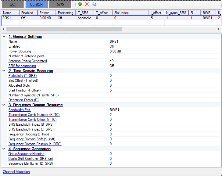
SRS Channel Table
Configure multiple SRS channels. Use the Add, Remove, and Copy buttons directly above to manage rows.
The conflict check between multiple SRSs is based on RE level. That is, if two SRSs use same RBs and symbols but different subcarriers, it is allowed.
1. General Settings
Name
Set the name for the channel.
Enabled
Enable or disable the channel or signal in a radio frame.
Power Boosting
Range: -40 to 40dB
Default: 0dB
Set the additional power boosting for the channel.
Number of Antenna Ports
Range: 1, 2, 4
Default: 1
Set the number of Antenna Ports used for SRS.
Antenna Port Generated
Enter a comma-separated string or click drop down arrow to set the mapping between physical antennas and logical antenna ports, the number of physical antennas is under Waveform Setup node.
SRS-for-positioning
Choices: On | Off
Default: Off
Set whether SRS is configured by the [SRS-for-positioning] IE.
2. Time Domain Resource
Periodicity (T_SRS)
Choices: 0 | 1 | 2 | 4 | 5 | 8 | 10 | 16 | 20 | 32 | 40 | 64 | 80 | 160 | 320 | 640 | 1280 | 2560 | 5120 | 10240 | 40960 | 81920
Default: 0
Select the Periodicity (T_SRS) for SRS, 0 means aperiodic.
For periodic SRS, Allocated Slots is read-only and automatically calculated by Periodicity and Slot Offset.
Slot Offset (T_offset)
Range: 0 to (Periodicity - 1)
Default: 0
Set the Slot Offset (T_offset) for SRS.
Allocated Slots
Range: 0 to number of slots in a frame for current numerology -1
Set the allocated slot index for the channel. There are 3 ways to configure:
-
To configure by individual index, use ',' as the delimiter, e.g. 0,1,2,3.
-
To configure by a range of index, use ':' to indicate the start index and the last index, e.g. 3:10 means 3,4,5,6,7,8,9,10.
-
To configure by a certain step, use two ':' to indicate the start index, the step and the last index, e.g. 0:4:12 means 0, 4, 8, 12.
These 3 configuration methods can be used in combination, by using ',' as the delimiter, e.g. 0,1,4:7,8:2:19 means index 0,1,4,5,6,7,8,10,12,14,16,18.
Start Position (l_offset)
Range: (N_symb_SRS - 1) to 13
Default: 5
Set the startPosition parameter for SRS, which determines the Symbol Start of SRS by l0 = N_symb_slot - 1 - l_offset.
Number of symbols (N_symb_SRS)
Range: 1, 2, 4, 8, 12 (Symbol Start + Number of symbols should be in the range of the last six symbols in this slot)
Default: 1
Set the number of symbols used for SRS. Number of Symbols can be {1, 2, 4}, and Symbol Start + Number of Symbols should smaller than the last symbol index in this slot
Repetition Factor (R)
Choices: 1 | 2 | 4 | 8 | 12 (should be equal or less than N_symb_SRS).
Default: 1
Set the Repetition Factor used for SRS.
3. Frequency Domain Resource
Bandwidth Part
Select a bandwidth part to be used for transmission, all the BWP names defined under BWP Setup node will be listed here.
Transmission Comb Number (K_TC)
Range: 2, 4, 8
Default: 2
Set the K_TC of the SRS.
Transmission Comb Offset (k_TC)
Range: 0 to K_TC
Default: 0
Set the k_TC of the SRS. The valid value for Transmission Comb Offset is [0…Transmission Comb Number-1].
SRS Bandwidth index (B_SRS)
Range: 0 to 3
Default: 0
Set the B_SRS of the SRS
SRS Bandwidth index (C_SRS)
Range: 0 to 63
Default: 0
Set the C_SRS of the SRS.
Frequency Hopping (b_hop)
Range: 0 to 3
Default: 0
Set the b_hop of the SRS.
Frequency Domain Shift (n_shift)
Range: 0 to 268
Default: 0
Set the n_shift of the SRS.
Frequency Domain Position (n_RRC)
Range: 0 to 67
Default: 0
Set the n_RRC of the SRS.
4. Sequence Generation
GroupSequenceHopping
Range: 0 to 2
Default: 0
Set the GroupSequenceHopping of the SRS.
Cyclic Shift Config (n_SRS_cs)
Range: 0 to 7 for K_TC = 2; 0 to 11 for K_TC = 4.
Default: 0
Set the n_SRS_cs for sequence generation
Sequence identity (n_ID_SRS)
Range: 0 to 65535
Default: 0
Set the n_ID_SRS for sequence generation.