UL FRC Config
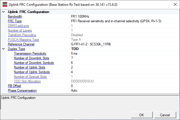
Bandwidth
Choices:
Downlink: Based on the Table 5.3.2-1 and 5.3.2-2 in 38.104.
Uplink: Based on the Table 5.3.2-1 in 38.101-1 and 38.101-2.
Selects the Bandwidth configuration for the carrier.
FRC Type
Choices: Based on the Annex A in 38.141
Selects the FRC Type.
DMRS-add-pos
Choices: 0 | 1
Sets the UL-DMRS-add-pos for A.3, A.4 and A.5 in 38.141.
Number of Layers
Choices: 1 | 2
Sets the Number of Layers for A.3 and A.4 in 38.141.
Transform Precoding
Default: Disabled
Enable or disable Transform Precoding for uplink.
PUSCH Mapping Type
Choices: Type A | Type B
Default: Type A
Sets the PUSCH Mapping type for the channel.
For FR1 A1/A2 and FR2 A1, it is fixed to Type A.
For FR1 A3/A4/A5, it is selectable.
For FR2 A3/A4/A5, it is fixed to Type B.
Reference Channel
Choices: Based on the Annex A in 38.141
Selects the Reference Channel based on the FRC Type (DMRS-add-pos and Number of Layers).
The table below summarizes the parameters of all the FRC channels:
FRC Type | DMRS | Number | Transform | PUSCH | Reference Channel | MCS | Coding Rate | Modulation |
|---|---|---|---|---|---|---|---|---|
G-FR1-A1 | 1 | 1 | Disabled | Type A | G-FR1-A1-1 to G-FR1-A1-9 | 4 | 308/1024 | QPSK |
G-FR1-A2 | 1 | 1 | Disabled | Type A | G-FR1-A2-1 to G-FR1-A2-6 | 16 | 658/1024 | 16QAM |
G-FR1-A3 | 1 | 1 | Disabled | Type A or B
| G-FR1-A3-8 to G-FR1-A3-14 | 2 | 193/1024 | QPSK |
1 | 2 | G-FR1-A3-22 to G-FR1-A3-28 | ||||||
1 | 1 | Enabled | G-FR1-A3-31 to G-FR1-A3-32 | |||||
G-FR1-A4 | 1 | 1 | Disabled | Type A or B
| G-FR1-A4-8 to G-FR1-A4-14 | 16 | 658/1024 | 16QAM |
1 | 2 | G-FR1-A4-22 to G-FR1-A4-28 | ||||||
G-FR1-A5 | 1 | 1 | Disabled | Type A or B | G-FR1-A5-8 to G-FR1-A5-14 | 20 | 567/1024 | 64QAM |
G-FR2-A1 | 1 | 1 | Disabled | Type A | G-FR2-A1-1 to G-FR2-A1-5 | 4 | 308/1024 | QPSK |
G-FR2-A3 | 0 | 1 | Disabled
| Type B | G-FR2-A3-1 to G-FR2-A3-5 | 2 | 193/1024 | QPSK |
0 | 2 | G-FR2-A3-6 to G-FR2-A3-10 | ||||||
0 | 1 | Enabled | G-FR2-A3-11 to G-FR2-A3-12 | |||||
1 | 1 | Disabled
| G-FR2-A3-13 to G-FR2-A3-17 | |||||
1 | 2 | G-FR2-A3-18 to G-FR2-A3-22 | ||||||
1 | 1 | Enabled | G-FR2-A3-23 to G-FR2-A3-24 | |||||
G-FR2-A4 | 0 | 1 | Disabled
| Type B | G-FR2-A4-1 to G-FR2-A4-5 | 16 | 658/1024 | 16QAM |
0 | 2 | G-FR2-A4-6 to G-FR2-A4-10 | ||||||
1 | 1 | G-FR2-A4-11 to G-FR2-A4-15 | ||||||
1 | 2 | G-FR2-A4-16 to G-FR2-A4-20 | ||||||
G-FR2-A5 | 0 | 1 | Disabled
| Type B | G-FR2-A5-1 to G-FR2-A5-5 | 20 | 567/1024 | 64QAM |
1 | 1 | G-FR2-A5-6 to G-FR2-A5-10 |
Duplex Type
Choices: TDD | FDD
Selects the duplex type.
When TDD is selected, several TDD parameters appear below. These TDD parameters are reset to default values whenever numerology changes or FR changes. (The default values are different for each numerology.)
Transmission Periodicity
Sets the periodicity of DL-UL pattern. The choices are related to numerology.
Number of Downlink Slots
Sets the number of consecutive full DL slots at the beginning of each DL-UL pattern. The range is related to the numerology and slot configuration period.
Number of Downlink Symbols
Range: 0 ~ 14 for Normal CP; 0 ~ 12 for Extended CP
Sets the number of consecutive DL symbols in the beginning of the slot following the last full DL slot.
Number of Uplink Slots
Sets the number of consecutive full UL slots at the end of each DL-UL pattern. The range is related to the numerology and slot configuration period.
Number of Uplink Symbols
Range: 0 ~ 14 for Normal CP; 0 ~ 12 for Extended CP
Sets the number of consecutive UL symbols in the end of the slot preceding the first full UL slot.
Number of Special Slots
Displays the number of special slots.
TDD Slot Allocation
Displays the TDD slot allocation for one period.
RB Offset
Choices: Based on the Annex A in 38.141.
Phase Compensation
For waveform playback mode:
Choices: Auto | Auto (Real-time) | Manual | Manual (Real-time) | Off
For real-time uplink mode:
Choices: Auto | Manual | Off
Default: Auto
Sets the phase compensation mode on baseband signal before upconversion.
Auto | Auto (Real-time): Use the RF frequency from the instrument node.
Manual | Manual (Real-time): Enter the RF frequency manually.
Off: Disable phase compensation on baseband signal.
(Real-time) means the phase compensation is done using FPGA inside the instrument.