Waveform Setup
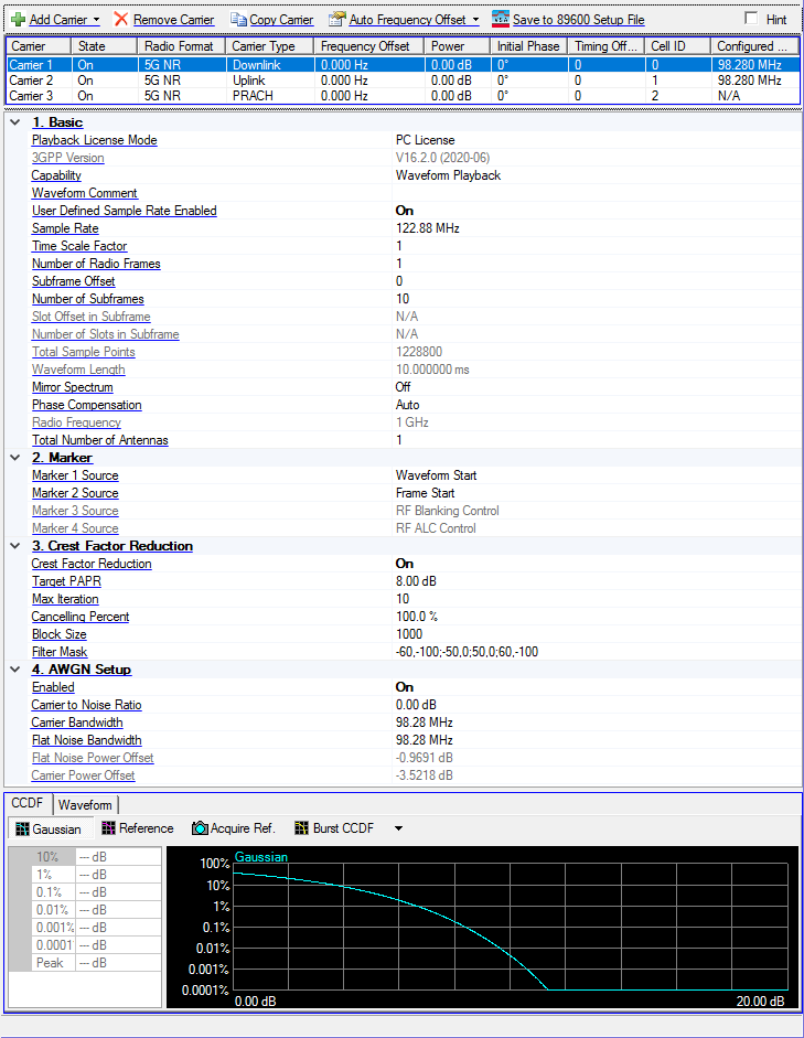
Click in the tree view to display the waveform pane shown below. The waveform setup pane is divided into three sections: Carrier Configuration Summary Table (top), Waveform Setup Property Grid (middle), and Graph View (bottom).
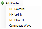
Add Carrier
Choices: NR Downlink | NR Uplink | NR PRACH | Continuous Wave
Click the  Add Carrier button to add a new 5G NR carrier to the list. New carrier will be assigned with a different Cell ID based on current carrier count.
Maximum carrier number is 16.
Remove Carrier
Click the Remove Carrier button to delete the selected 5G NR carrier from the list.
Copy Carrier
Click the Copy Carrier button to copy the selected 5G NR carrier and append it to the list.
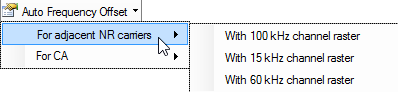
Auto Frequency Offset
This drop-down menu allows you to automatically set the frequency offset for each carrier, based on section 5.4.1 of 38.104, to get the expected channel spacing.
Save to 89600 Setup File
This feature saves the Carrier configuration as a 89600B VSA setup file, simplifying VSA configuration so you can quickly demodulate the signal. For information about setup file settings, refer to 89600 Setup File Setting.
Carrier Configuration Summary Table
This table enables you to view the key properties for each carrier in the waveform. You can also add or delete carriers using the buttons above the table (see descriptions above). Double-click a carrier row to access the properties for that carrier.
1. Basic
Playback License Mode
Choices: PC License | Instrument License
Default: PC License.
Select the playback license mode. If no PC license is available, only Instrument License can be used.
Licensing of Signal Studio Pro Software
|
|
N76xxAPPC |
N76xxEMBC |
|
|
License File Presence |
PC (running Signal Studio Pro software) |
Signal Generator |
|
|
Playback License Mode |
Two selections (PC License | Instrument License) |
One selection (Instrument License) |
|
|
Available Software Functions |
Live Connection to Signal Generator |
ü |
ü |
|
VSA .SETX Export |
ü |
ü |
|
|
Programming API |
ü |
ü |
|
|
Waveform Export |
ü |
ü |
|
License Mode Switching
You can switch waveform playback license mode to take advantage of an instrument license, even when a PC license is available with GUI parameter "Playback License Mode" under "Waveform Setup" node, "Basic" group.
-
Playback License Mode has 2 selections: PC License | Instrument License
-
When "PC License" is selected, "Waveform Name" should be hidden (you cannot change the waveform name). And Waveform Name API is read-only (not accepting waveform name change).
-
When valid PC license (N7631APPC) exists, this parameter is active and you can choose either one. Default is "PC License."
-
When valid PC license does NOT exist, this parameter is read-only and "Instrument License" mode is selected.
-
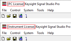
Window
caption displays "[PC License]" or "[Instrument License]" to indicate the currently selected license mode.
3GPP Version
Default (fixed): V16.2.0 (2020-06)
This read-only field display the supported version of 3GPP specifications:
TS 38.211 Physical Channels and Modulation
TS 38.212 Multiplexing and Channel Coding
TS 38.213 Physical Layer Procedures for Control
TS 38.214 Physical Layer Procedures for Data
Capability
Choice: Waveform Playback | Real-time Uplink
Default: Waveform Playback
Select the capability of 5G signal simulation.
-
Waveform Playback mode means Signal Studio will generate the IQ waveform, using the PC, and then download it to instrument.
Upon selecting this mode, the 5G NR Uplink node in the tree view changes to Waveform Setup and many more parameters appear. Additionally, multicarrier editing buttons appear above the parameters pane, replacing the instrument control buttons.
-
Real-time Uplink mode means the IQ waveform is generated inside the instrument. It can receive HARQ feedback from AUX port for loop back test.
Upon selecting this mode, the Waveform Setup node in the tree view changes to 5G NR Uplink and only the Basic property table is displayed with a subset of parameters. Additionally, instrument control buttons appear above the parameters pane, replacing the multicarrier editing buttons.
Waveform Comment
Enter the comment for the waveform, up to 32 characters.
User Defined Sample Rate
Choice: On | Off
Default: Off
Enable or disable the User Defined Sample Rate. If enabled, the Sample Rate can be edited to input the user defined sample rate.
Sample Rate
Range: 20 MHz to 12 GHz
Default: 122.88 MHz (61.44 MHz if numerology = 15 kHz)
This parameter is read-only. The sample rate is automatically calculated to meet the requirement of waveform settings and connected instrument.
If User Defined Sample Rate is disabled, the sample rate is automatically calculated to meet the requirement of waveform settings and connected instrument, otherwise this value can be editable to input user-defined sample rate.
-
If the connected instrument is M8190A Direct mode, the auto calculated sample rate is larger than 125 MHz to meet the instrument limitation.
-
If the connected instrument is M8190A DUC mode, the sample rate is auto calculated based on the interpolated mode to meet the instrument limitation.
Time Scale Factor
Range: 0.001 to 1000
Default: 1
Set the Time Scale Factor of the sample rate.
When Phase Compensation is set to Auto (Real-time) or Manual (Real-time) this parameter is read-only and set to 1.
Number of Radio Frames
Default: 1
If the carrier is a downlink carrier and SSB is enabled, change this parameter to match the SSB period, otherwise a warning is generated.
Subframe Offset
Range: 0 to 9
Default: 0
Set the subframe offset to generate partial radio frame when the Number of Radio Frames is 1.
Number of Subframes
Range: 1 to (10 - Subframe Offset)
Default: 10
Set the number of subframes to generate partial radio frame when the Number of Radio Frames is 1.
Slot Offset in Subframe
Set the slot offset in subframe to generate partial subframe when the number of subframe is 1. This parameter is only applicable for single downlink/uplink carrier and single numerology case.
The range is based on the numerology of the carrier.
Number of Slots in Subframe
Set the number of slots in subframe to generate partial subframe when the number of subframe is 1. This parameter is only applicable for single downlink/uplink carrier and single numerology case.
The range is based on the numerology of the carrier.
Total Sample Points
Sets or displays the number of sample points in the waveform. This value can be edit if there is no carrier in the waveform, otherwise it is read-only and will be automatically updated with waveform setting changes.
Waveform Length
Display the waveform length in seconds. This value is read-only and will be automatically updated with waveform setting change
Mirror Spectrum
Choices: On | Off
Default: Off
If enabled, I and Q data of waveform are swapped to make the mirror spectrum. PSG has I/Q Swap at 20G~28.5G band, so this should be enabled for testing signal from PSG at 28 GHz.
Phase Compensation
Choices: Auto | Auto (Real-time) | Manual | Manual (Real-time) | Off
Default: Auto
Set the phase compensation mode on the baseband signal before upconversion. Phase compensation is not applicable for PRACH carrier.
-
Auto: Use the RF frequency from the instrument node.
-
Auto (Real-time): Use the RF frequency from the instrument node. (See section below.)
-
Manual: Enter the RF frequency manually.
-
Manual (Real-time): Enter the RF frequency manually. (See section below.)
-
Off: Disable phase compensation on baseband signal.
Auto (Real-time) and Manual (Real-time) Information
-
Only N5172B/N5182B signal generators are supported.
-
If your instrument has an older firmware version that does not include the embedded phase-compensation capability, or does not have the latest version of this capability, the N7631C software deploys a real-time application called “Phase Compensation” into the instrument and then restarts the instrument.
-
Phase compensation is calculated using the FPGA inside the instrument.
-
Time Scale Factor is read-only and set to 1.
-
Crest Factor Reduction is read-only and set to Off.
-
Only one carrier and single numerology are supported. If these requirements are not met in the configuration, an
error appears prior to waveform generation.
See also, Real-time Phase Compensation Using SCPI.
Radio Frequency
Range: 0 to 100 GHz
Default: 1 GHz
Set the Radio Frequency when doing the phase compensation on baseband signal, it is automatically coupled with the frequency of instrument when Phase Compensation is set to Auto, and can be edited when Phase Compensation is set to Manual, but not visible when Phase Compensation is Off.
Total Number of Antennas
Choices: 1 | 2 | 3 | 4
Default: 1
Sets the number of antennas for each generation. It is used for MIMO configuration. The "Antenna Port(s) Generated" parameter in the Channel Setup node for DL-SCH, ULSCH, CSI-RS, and SRS allows you to configure the mapping between antenna and logical antenna port.
2. Marker
Marker 1 Source
Choices: Waveform Start | Frame Start | RF Blanking Control | RF ALC Control
Default: Waveform Start
Select the source for marker 1.
-
Waveform Start: It indicates the beginning of the waveform.
-
Frame Start: It indicates the beginning of each frame in the waveform.
-
RF Blanking Control: It indicates the burst part in the waveform.
-
RF ALC Control: It indicates the part used for ALC control in the waveform.
Marker 2 Source
Choices: Waveform Start | Frame Start | RF Blanking Control | RF ALC Control
Default: Frame Start
Select the source for marker 2.
-
Waveform Start: It indicates the beginning of the waveform.
-
Frame Start: It indicates the beginning of each frame in the waveform.
-
RF Blanking Control: It indicates the burst part in the waveform.
-
RF ALC Control: It indicates the part used for ALC control in the waveform.
Marker 3 Source
Displays the source for marker 3. RF Blanking Control is always used as Marker 3 source.
Marker 4 Source
Displays the source for marker 4. RF ALC Control is always used as Marker 4 source.
3. Crest Factor Reduction
Crest Factor Reduction
Choices: On | Off
Default: Off
Enable or disable the crest factor reduction for the waveform. When enabled, peak cancellation algorithm is used to subtract a weighted version of the cancellation pulses from the original input signal. It strikes a balance between the out-of-band emission and in-band waveform quality when reducing the PAPR of the signal.
When Phase Compensation is set to Auto (Real-time) or Manual (Real-time) this parameter is read-only and set to Off.
Target PAPR
Range: 3 to 100 dB
Default: 8 dB
Set the PAPR value to achieve after crest factor reduction.
Max Iteration
Range: 1 to 100
Default: 10
Specify the maximum times of iteration. With the increase of iteration, the PAPR value should converge to a steady level.
Cancelling Percent
Range: 0 to 100%
Default: 100%
Specify the percentage of the cancellation pulses that can be removed.
Block Size
Range: 20 to Waveform Total Sample Points
Default: 1000
Block is the range so that a single cancellation pulse can be identified. If the waveform length is L, and the block size is B, then the number of blocks is N=floor(L/B)+1. Therefore, there will be N pulses at most to be removed.
Filter Mask
Bring up the filter mask editor to define a filter response in frequency domain. In the table, the frequency points must be entered with an order of increasing frequency in unit of MHz, and its corresponding amplitude is in unit of dB. When generating this filter mask, the frequency points between the specified points are linearly interpolated. When carrier number or carrier frequency offset in the waveform is changed, this table is automatically updated. A need may arise to adjust the mask manually to fit the actual signal bandwidth.
4. AWGN Setup
Enabled
Choices: On | Off
Default: Off
Enable or disable additive white gaussian noise (AWGN) in the waveform.
Carrier to Noise Ratio
Range: -100 to 100 dB
Default: 0 dB
Set the carrier to noise ratio, where the carrier is the one with 0dB power.
Carrier Bandwidth
Range: 1 to Sample Rate
Set the waveform bandwidth, it is automatically updated when parameters related to frequency domain location changes, otherwise user can input self-defined value.
Flat Noise Bandwidth
Range: 1 to Sample Rate / 1.25
Set the noise bandwidth.
Flat Noise Power Offset
Display the flat noise power offset compare to the signal generator power.
Carrier Power Offset
Displays the carrier power offset compare to the signal generator power.
Graph View
The graph view displays several different representations of the generated waveform. For more information, see Graph View.