The DPD Wizard is used to set up and create a DPD waveform.
In this topic:
Programming Examples:
Direct DPD
DPD Modeling
DPD Model From File
On the VNA front panel, press Meas > S-Param > Meas Class....
Select Modulation Distortion or Modulation Distortion Converters, then either:
OK delete the existing measurement, or
New Channel to create the measurement in a new channel.
The Modulation Distortion or Modulation Distortion Converters dialog is displayed.
Accessing DPD Settings |
|
|
Using Hardkey/SoftTab/Softkey |
Using a mouse |
|
|
|
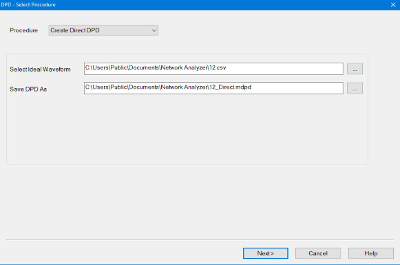
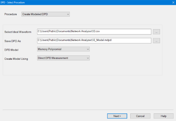
Dialog for Create Direct DPD
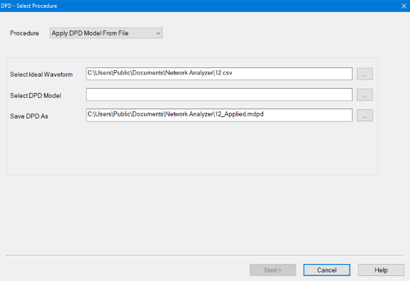
Dialog for Apply DPD Model From File
Procedure Create Direct DPD - Creates a Direct DPD waveform used to determine the maximum possible improvement in EVM using DPD. Create Modeled DPD - Creates a DPD model and a Modeled DPD waveform used to test the DUT performance when using the DPD model. Apply DPD Model From File - The user will supply an Ideal Waveform file and a DPD Model file. The Model will be applied to the Ideal Waveform to create a Modeled DPD Waveform. This allows a user-supplied model to be tested on multiple waveforms. 
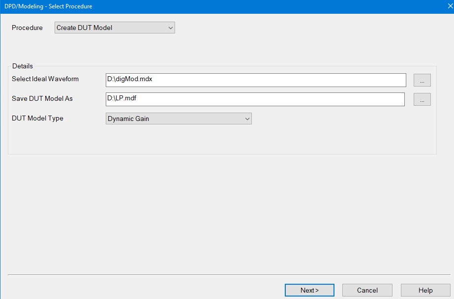
Create DUT Model - Creates a model of the DUT. Select Ideal Waveform - User selects the ideal modulation waveform file name. The default file is the modulation file currently selected in the Modulate tab of the Modulation Distortion Setup dialog. Select DPD Model - Selects a DPD Model from a pre-existing file (*.mdpd). Save DPD As - Saves the DPD Model as a *.mdpd file type (zipped file) containing the following files:
Save DUT Model As - Saves the DUT Model as a *.mdpd (Modeling FIles) or *.mdf (SystemVuew MDIF). Only Visible when Create DUT Model are the selected Procedure. Modeling FIles (*.mdpd) is a zip file containing the 7 files below:
SystemVue MDIF (*.mdf) - Choose this will save MDIF file for SystemVue & ADS.
If the ideal waveform are defined as an encrypted .wfm file and user saves the model as
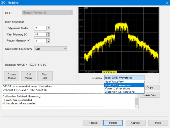
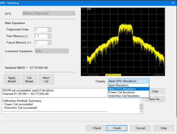
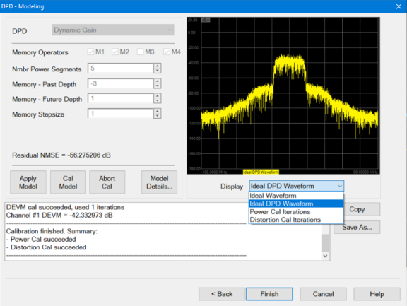
DPD Model Type - User Selects the DPD model. Only visible when Create Modeled DPD and Create DUT Model are the selected Procedure. Memory Polynomial - DPD model that uses the memory polynomial algorithm to create the model. Dynamic Gain - DPD model that uses both the gain and the memory operators to generate the dynamic gain algorithm. Note: Dynamic Gain of measurements above 50 GHz requires the S93110B Active Hot Parameters license Create Model Using - Only visible when Create Modeled DPD is the selected Procedure. Direct DPD Measurement - The DPD model is fit to the Direct DPD measurement. Direct DPD From File - The Direct DPD waveform from the file is used to fit the model. This choice is only available if the Ideal Waveform file contains a Direct DPD waveform. 
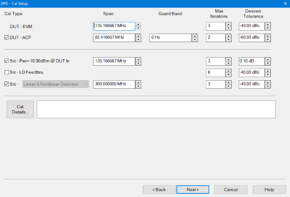
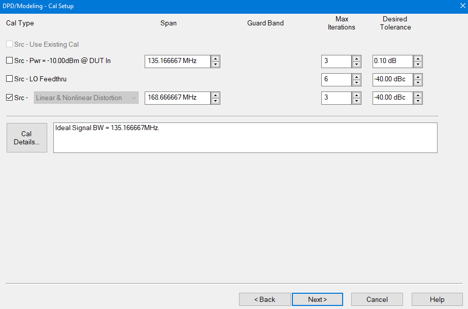
Next > button - Accesses the Cal Setup dialog.
|
|||||||||||||||||||||||||||||||||||||||
|
|
|
When Create Direct DPD and Create Modeled DPD is the selected Procedure.
When Create DUT Model is the selected Procedure.
DUT - EVM - Value used to optimize distortion at the DUT output relative to the Ideal Waveform. DUT - ACP - Value used to optimize the upper and lower ACP bands at the DUT output. Src - Use Existing Cal - If the Ideal Waveform .mdx includes a source calibration, then this selection is available when Create DUT Model is the selected Procedure. If turned ON, then all other source cal choices (below) will be grayed out and disabled. Src - Power = -10.00dBm@DUT In - Calibrates the source power level at the -10dBm DUT input. Src - LO Feedthru - Calibrates the source LO feedthru at the DUT input. Src - Linear & NonLinear Distortion - Corrects linear and nonlinear distortion of the source at the DUT input. Span - Sets the span of the modulated signal or can be defined to also include upper and lower ACP bands. Guard Band - (DUT - ACP only) Sets the frequency delta from the edge of the carrier to the beginning of the ACP Span. The default is set to zero. This value is positive for both ACP Lower and ACP Upper. Max Iterations - The calibration routine uses successive approximation. This value sets the maximum number of iterations used by the calibration routine. Desired Tolerance - Sets the desired tolerance for each calibration. Cal Details - Accesses the Cal Details dialog < Back button - Accesses the DPD Select Procedure dialog. Next > button - Accesses the Calibrate dialog.
|
|
|
DAC Scaling - Sets the Scale value used in the modulated source. This ensures that the DAC filter does not output a signal that is larger than the DAC's maximum output level, which can cause distortion in the system. Setting the scaling factor to 100% will usually cause excessive distortion. The default value is equal to the value in the Ideal Waveform file. If no value exists, the default value is 70%. Limit PAPR Expansion To - Limits the peak-to-average power ratio (PAPR) expansion allowed in the DPD waveform. The DPD process will hard limit the sampled time-domain DPD waveform so that the PAPR is always less than the Ideal Waveform PAPR plus the Max PAPR Expansion If the Ideal Waveform PAPR = XdB, then the DPD Waveform PAPR £ Xdb + (PAPR Expansion). The default value of PAPR Expansion is 2 dB. Backoff For Linear Gain Measurement = [Cal Pwr] - This defines the power level used during the linear S21 measurement for the DPD Dynamic Gain model. The default value is 20 dB. During Direct DPD, Measure DUT Linear Gain - By default is set to ON. If ON, the DirectDPD process will measure and save the DUTLinearGain.csv in the output file. This linear gain may be used later if the user creates the Dynamic Gain model using DirectDPD From File.
|
|
Note: This dialog does not apply to the Apply DPD Model From File procedure. The modulation source calibration will be performed at the DUT Output by iterating until the DUT Output signal matches the Ideal Waveform. Next will measure Direct DPD waveform at DUT Input. Calibrate button - Starts the calibration. Abort button - Aborts the measurement in process. Display - Choose from the following display selections: Ideal Waveform is the original waveform selected in the DPD Select Procedure dialog. Power Cal Iterations displays traces used during the power calibration. Distortion Cal Iterations displays traces used during the distortion calibration. Notch Cal Iterations displays traces used during the DUT-ACP calibration. Copy button - Copies information displayed in the status window to the clipboard. Save As... button - Saves the information displayed in the status window to a *.txt file. < Back button - Accesses the Cal Setup dialog. Finish button (Create Direct DPD only) - When completed, click on the Finish button to perform the following:
Next button - Accesses the Modeling dialog to set up and create the DPD model.
|
|
|
Create Modeled DPD procedure with Memory Polynomial DPD model.
Apply Modeled DPD procedure with Memory Polynomial DPD model.
DPD Model - Displays the DPD model. The DPD model selection must be done on the first page of the wizard, see the Dialog for Create Modeled DPD.
Main Equations Polynomial Order - Defines the order of the polynomial equation used to model the DUT nonlinearity.
Past and Future Memory The memory polynomial converts the input Ideal Waveform into the DPD Modeled Waveform. These waveforms are a series of samples versus time. At a given time T, the DPD Modeled Waveform sample is calculated from past (T-1, T-2, etc.), present (T), and future (T+1, T+2, etc.) samples of the Ideal Waveform. A memory polynomial uses past and future samples of the input waveform to calculate the present value of the output waveform. Past Memory (-) - Defines the number of input past time samples to use for calculating the current output sample. This is an integer less than or equal to zero. If set to zero, then there is no past memory and past samples will not affect the model. Future Memory (+) - Defines the number of input future time samples to use for calculating the current output sample. This is an integer greater than or equal to zero. If set to zero, then there is no future memory and future samples will not affect the model.
Crossterm Equations The crossterm equations combine samples measured at different times, providing more complex memory equations than the main Memory Polynomial memory equations. Auto - Perform crossterm calculations using default values for the crossterm equation. The Crossterm Order is set equal to the Main Equation Order. The Crossterm Memory is set equal to the Main Equation Memory. The Crossterm Past Delay is set to -1 and the Future Delay is set to +1. Off - Do not use crossterm calculations. Create Model button - Creates the DPD Model file from the settings in the Modeling dialog and creates the "MyDPD_IdealDPD" waveform. Apply Model button - Creates the Modeled DPD Waveform from a user-supplied Ideal Waveform file and a DPD Model file. The DPD Model will be applied to the Ideal Waveform to create the Modeled DPD Waveform. Cal Model - If requested , will calibrate source power level at DUT input, source LO Feedthru, and linear and nonlinear distortion of the source at the DUT input. Abort button - Aborts both the create model and cal model processes. Display - Choose from the following display selections: Ideal Waveform displays the original waveform selected in the DPD Select Procedure dialog. Ideal Modeled DPD displays the DPD waveform calculated by applying the model to the Ideal Waveform. Power Cal Iterations displays traces used during the power calibration. Distortion Cal Iterations displays traces used during the distortion calibration.
Create Modeled DPD procedure with Dynamic Gain DPD model. Note: License S94802B "Millimeter-wave component modeling" is required for the use of DPD with Dynamic Gain above 50 GHz.
Apply Modeled DPD procedure with Dynamic Gain DPD model. Note: License S94802B "Millimeter-wave component modeling" is required for the use of DPD with Dynamic Gain above 50 GHz.
DPD Model - Displays the DPD model. The DPD model selection must be done on the first page of the wizard, see the Dialog for Create Modeled DPD. Memory Operators - Selects the memory operators used for characterizing the device. By default, operators M1,M2 and M4 were selected. Nmbr Power Segments - Specifies the number of power segments. The input power range is split into separate segments, where each segment has its own look-up-table. Memory - Past Depth -Defines the memory depth for past samples used with the memory operators. This is an integer less than or equal to zero. Memory - Future Depth - Defines the memory depth for future samples used with the memory operators. This is an integer more than or equal to zero. Memory Stepsize - Defines the step size between samples used. A Memory Stepsize of 2 means every other sample will be used. If (Future Memory - Past Memory)/(Memory Stepsize) is not an integer, then (Future Memory) will be increased to make it an integer. Create Model - See above. Apply Model - See above Cal Model - See above. Abort - See above. Model Details - Accesses the Model Details dialog. Display - See above.
Buttons Copy button - Copies information displayed in the status window to the clipboard. Save As... button - Saves the information displayed in the status window to a *.txt file. < Back button - Accesses the Modulation Cal dialog. Finish button - When completed, click on the Finish button.
Create DUT Model procedure with Memory Polynomial DUT model.
DUT Model - Displays the DUT model. The DUT model selection must be done on the first page of the wizard, see the Dialog for Create DUT Model. Main Equations Polynomial Order - Defines the order of the polynomial equation used to model the DUT nonlinearity.
Past and Future Memory The memory polynomial converts the input Ideal Waveform into the DPD Modeled Waveform. These waveforms are a series of samples versus time. At a given time T, the DPD Modeled Waveform sample is calculated from past (T-1, T-2, etc.), present (T), and future (T+1, T+2, etc.) samples of the Ideal Waveform. A memory polynomial uses past and future samples of the input waveform to calculate the present value of the output waveform. Past Memory (-) - Defines the number of input past time samples to use for calculating the current output sample. This is an integer less than or equal to zero. If set to zero, then there is no past memory and past samples will not affect the model. Future Memory (+) - Defines the number of input future time samples to use for calculating the current output sample. This is an integer greater than or equal to zero. If set to zero, then there is no future memory and future samples will not affect the model.
Crossterm Equations The crossterm equations combine samples measured at different times, providing more complex memory equations than the main Memory Polynomial memory equations. Create Model button - When clicked does the following: (1) Create Model : Enable source correction, measure Corrected DUT In and Corrected DUT Out and create DUT model which maps from Corrected DUT In to Corrected DUT Out (2) Create Waveforms for display purposes only: - Pass deal Waveform through DUT Model to create Ideal Modeled Waveform, - Pass Corrected DUT In through DUT Model to create Corrected Modeled DUT Out and calculate errors between Corrected DUT Out - Corrected Modeled Out to display the residual NMSE.
Abort button - Aborts the model creation process. Display - Choose from the following display selections: Ideal Waveform Displays the original waveform selected in the DPD Select Procedure dialog. DUT Pin Measured Displays the measured DUT input DUT Pout (Meas & Model) Displays two traces for the DUT output. Meas Pout" is the measured DUT Pout. "Model Pout" is the result of applying the DUT model to the Measured DUT Pin. DUT Model Error Display the difference between "Meas Pout" and "Model Pout" as described above.
Create DUT Model procedure with Dynamic Gain DUT model
DUT Model - Displays the DUT model. The DUT model selection must be done on the first page of the wizard, see the Dialog for Create DUT Model. Memory Operators - Selects the memory operators used for characterizing the device. By default, operators M1,M2 and M4 were selected. Nmbr Power Segments - Specifies the number of power segments. The input power range is split into separate segments, where each segment has its own look-up-table. Memory - Past Depth -Defines the memory depth for past samples used with the memory operators. This is an integer less than or equal to zero. Memory - Future Depth - Defines the memory depth for future samples used with the memory operators. This is an integer more than or equal to zero. Memory Stepsize - Defines the step size between samples used. A Memory Stepsize of 2 means every other sample will be used. If (Future Memory - Past Memory)/(Memory Stepsize) is not an integer, then (Future Memory) will be increased to make it an integer. Create Model button - See above Abort button - See above Display - See above Model Details - Opens the Model Details dialog.
Buttons Copy button - Copies information displayed in the status window to the clipboard. Save As... button - Saves the information displayed in the status window to a *.txt file. < Back button - Accesses the Modulation Cal dialog. Finish button - When completed, click on the Finish button.
|
|
|
Interpolation Type - Selects the interpolation type used in the AM/AM and AM/PM segments. Choose Spline, Cubic or Linear, default is Cubic. Min Points Per Power Segment - Sets the min points used in the AM/AM and AM/PM segments. The default is 100. If the user select too many segments, then the number of segments will be reduced until each segment has at least " min points". Optimize DPD Model - If selected, DPD will iterate over the Past Memory, Future Memory and Number of Power Segments to find the lowest NMSE.
|