Last updated: 2010-03-10
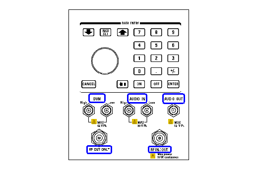
Click on the blue circle for the detailed descriptions of this interface.

The input to the audio analyzer is a floating input differential amplifier. Both the AUDIO IN High and AUDIO IN Low BNC connectors should be connected to provide noise immunity. Refer to the Technical Specifications in the Application Datasheet for more information.
This BNC connector accesses the test set's Audio Generator and FM Demod signals. The Audio Generator is used to stimulate a system to measure audio performance characteristics. The FM Demod allows the user to access the demodulated FM signal for external analysis and baseband processing. Refer to the Technical Specifications in the Application Datasheet for more information.
|
|
There will be no guaranteed performance for the signal present at the AUDIO OUT connector when FM Demod signal is selected for output. |
Not functional for this release.
This Type-N connector is the default path for all RF signals out of the test set, and is always used as the RF input. Refer to the Technical Specifications in the Application Datasheet for more information. See also RF OUT ONLY .
|
|
This port cannot be used with the E1960A GSM test application or with the GSM personality in a test application suite (such as the E1985A GSM_AMPS/136_GPRS suite). |
This Type-N connector is an optional path for all RF signals out of the test set. It is intended to be used for duplexed testing. Front panel selection of this port is provided by the RF Output Port ( F6 ) control on the System Config screen, and by the RFGenerator:OUTPut[:DESTination] IO/OUT command. The same amplitude offsets and output power settings are used for either selected port (RF IN/OUT or RF OUT ONLY). Refer to the Technical Specifications in the Application Datasheet for more information.