Last updated: 2014-11-28
Spectrum Monitor (SMON) Description
How Do I Use the Spectrum Monitor?
The Spectrum Monitor (SMON) can be used to locate, identify and measure transmitted signals from a device under test. The Spectrum Monitor can be used while a call is in progress.
The Spectrum Monitor is intended to be used for indication only. The Spectrum Monitor does not have the same level accuracy specifications as other measurements provided by the test set, and should therefore not be used when parametric accuracy is required (for example, calibration of a mobile). It is recommended that you use the other wireless format-specific measurements when you require accurate parametric measurements.
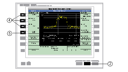
From the test set's front panel, the Spectrum Monitor can be accessed by pressing the Instrument Selection key, then selecting Spectrum Monitor . If you require more details on manual operation of the Spectrum Monitor, see How Do I Use the Spectrum Monitor? .
The Spectrum Monitor has the following two modes of operation:
Swept mode, in which the X axis represents frequency , and the Y axis represents absolute amplitude.
Zero span mode, in which the X axis represents time and the Y axis represents absolute amplitude.
You can use the markers on the Spectrum Monitor's graphical display to set the expected frequency and power levels that are used by the test or lab application for parametric measurements.
The center frequency used by the Spectrum Monitor is initially set at the expected frequency maintained by the test set's base station emulator. The expected frequency range is 292.5 MHz to 2700 MHz.
The range of frequencies which the spectrum monitor is calibrated to measure is determined by the range of traffic band frequencies supported by the specific test or lab application that is currently running. For example, if you are using the GSM Test Application, any of the frequencies used by the GSM traffic bands are available for you to monitor accurately. You can view signals which fall outside of any of the frequencies used by GSM, but the Spectrum Monitor will not be calibrated.
Frequency binning is used when the Spectrum Monitor divides the frequency span by the number of display points such that each bin contains a segment of the frequency span. Within each frequency bin, a single value representing each frequency bin is displayed on the test set's screen. The algorithm used to find the value that represents each frequency bin is determined by the detection method. There are three detection methods available in the test set's Spectrum Monitor:
Peak Detection
The largest spectral component in the frequency bin is used to represent each bin.
Sample Detection
The last spectral component in the frequency bin is used to represent each bin.
RMS Detection
The sum of the power across the frequency bin is used to represent each bin.
The resolution bandwidth can be used to resolve two or more closely spaced signals as long as the resolution bandwidth is less than the difference between the spectral components. A resolution bandwidth greater than or equal to the signal bandwidth can be used to measure the total power of a signal.
Refer to Frequency Span, Resolution Bandwidth and Dynamic Range below. When the Resolution Bandwidth Coupling State is OFF, the Frequency Span and the Resolution Bandwidth can be set to any value in their respective columns, and Resolution Bandwidth setting determines the Displayed Dynamic Range. When the Resolution Bandwidth Coupling State is On, the Resolution Bandwidth and Displayed Dynamic Range settings are coupled with the Frequency Span setting. For example, if the Frequency Span is 100 MHz, the test set automatically sets the Resolution Bandwidth to 5 MHz and the Displayed Dynamic Range to 55 dB.
Frequency Span, Resolution Bandwidth and Dynamic Range
|
Frequency Span |
Resolution Bandwidth |
Displayed Dynamic Range |
|
100 MHz |
5 MHz |
50 dB |
|
80 MHz |
1 MHz |
55 dB |
|
40 MHz |
300 kHz |
60 dB |
|
20 MHz |
100 kHz |
65 dB |
|
12 MHz |
100 kHz |
65 dB |
|
10 MHz |
100 kHz |
65 dB |
|
5 MHz |
30 kHz |
70dB |
|
4 MHz |
30 kHz |
70 dB |
|
2.5 MHz |
10 kHz |
75 dB |
|
1.25 MHz |
3 kHz |
80 dB |
|
500 kHz |
1 kHz |
80 dB |
|
125 kHz |
300 Hz |
80 dB |
|
0 Hz (zero span mode) |
100 kHz |
65 dB |
|
300 kHz |
60 dB |
|
|
1 MHz |
55 dB |
The Spectrum Monitor can return either single or averaged results.
If you set the averaging state OFF then the trace represents a single measurement sweep.
If you set the averaging state ON, and the averaging count number to a value greater than one, then the trace represents the rolling average of the specified number of sweeps.
The Spectrum Monitor will complete and meet its accuracy specifications under the following input signal conditions.
The signal is within 40 dB of the reference level.
The measurement frequency is within the traffic band frequencies supported by the specific lab or test application that is currently running, and the expected frequency is tuned to the carrier.
Triggering choices available for the Spectrum Monitor are Immediate, Protocol, RF Rise, and External. For a detailed description of the trigger source, see Trigger Source
The following procedure shows a typical usage of the spectrum monitor in each of its two modes of operation; Swept Mode and Zero Span mode.
Establish a call with the mobile.
Press the Instrument selection key.
Select Spectrum Monitor.

The spectrum monitor is displayed with the default settings as shown above. The center frequency is initially set at the expected frequency maintained by the test set's base station emulator. The Swap Window Positions ( F5 ) key is only displayed when other measurements are active at the same time as the spectrum monitor.
Set the axis control as needed for your testing situation using the Frequency Span ( F1 ), Reference ( F2 ), and dB/div ( F3 ) keys. See Frequency Span, Resolution Bandwidth and Dynamic Range for the valid Frequency Span entries. To set the reference level manually ( Auto is the default), press the Reference ( F2) key then use the DATA ENTRY keys to enter the value you want.
Press the Trigger Setup ( F4 ) key to access the Trigger Setup menu.
Set the trigger settings to meet your testing needs. For example:
If you want the Spectrum Monitor to sweep immediately and continuously, ensure that Trigger Arm ( F3 ) is set to Continuous .
If you want to use external triggering, so that the Spectrum Monitor is triggered from a signal applied to the TRIG IN connector on the test set's rear panel, set Trigger Source ( F1 ) to External .
Trigger Delay ( F2 ) allows you to specify the point, relative to the trigger event where samples are taken (a negative trigger delay value collects pre-trigger samples). The same trigger delay setting is used for swept mode and zero span mode.
Res Bw allows you to set the resolution bandwidth. If you want the resolution bandwidth coupled with the with the Frequency Span , set this field to AUTO by pressing the gray DATA ENTRY softkey labeled ON , otherwise use the knob or the numeric DATA ENTRY soft keys to set the resolution bandwidth. See Frequency Span, Resolution Bandwidth and Dynamic Range to find the valid entries for the resolution bandwidth while in swept mode. Note that changing the resolution bandwidth does not modify the zero span resolution bandwidth setting.
Press the Return ( F6 ) key to exit the Trigger Setup menu.
Press the Display ( F6 ) key to access the display settings.
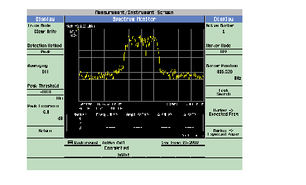
A typical spectrum monitor trace display is shown above. In this case, the Display menu is open allowing you to access all of the display control settings using the ( F1 ) through ( F12 ) keys.
The following list provides examples of some of the settings you may want to adjust:
Detection Method ( F2 ) determines the algorithm used to find the value that represents each frequency bin. See Detection Method for more information.
Peak Threshold ( F4 ) and Peak Excursion ( F5 ) set the peak threshold and peak excursion levels respectively. A peak is identified by using the peak threshold and peak excursion value. A point is only marked as a peak if it rises and falls more than the peak excursion value from the peak threshold value.
Marker Mode ( F8 ) sets the mode of the active marker. Position mode activates a single frequency marker. Delta mode freezes the active marker at its current location and uses it as a reference marker. A second marker is created at the position of the reference marker and is used as a delta marker, reporting any change in amplitude or frequency from that of the reference marker.
Peak Search ( F10 ) moves the active marker to the highest peak on the spectrum monitor display, returning the numeric amplitude and frequency values.
Marker -> Expected Freq ( F11 ) sets the base station emulator's expected frequency to the frequency of the active marker.
Marker -> Expected Power ( F12 ) sets the base station emulator's expected power level to the amplitude of the active marker.
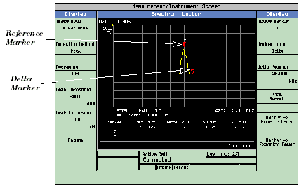
A typical swept mode spectrum monitor display is shown above. In this case, the active marker is marker 1, which is set to Delta mode.
Press the Return ( F6 ) key to exit the Display menu.
To set the spectrum monitor to zero span mode, press the Frequency Span ( F1 ) key and use the numeric DATA ENTRY keys to enter a value of 0 MHz , or use the down-arrow key to reduce the span to zero.
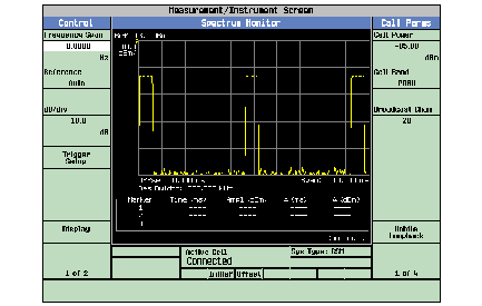
A typical zero span mode spectrum monitor display is shown above. Like swept mode, the Y-axis represents absolute amplitude. However, the X-axis now represents time rather than frequency.
Press the Trigger Setup ( F6 ) key. In zero span mode, additional trigger setup controls are available to you:
If you want to change the view window over which you are looking at the signal, use the Time Span ( F8 ) and Time Offset ( F9 ) keys. The measurement is made for the duration of the time span, beginning at the time defined by the trigger event plus the trigger delay plus the time offset.
If you want to change the resolution bandwidth, press the Zero Span RBW ( F7 ) key and select a value. (To measure the total power of a signal you must select a resolution bandwidth greater than or equal to the signal bandwidth.) See Frequency Span, Resolution Bandwidth and Dynamic Range to find the valid entries for the resolution bandwidth while in zero span mode. Note that changing the zero span resolution bandwidth does not modify the swept mode resolution bandwidth.
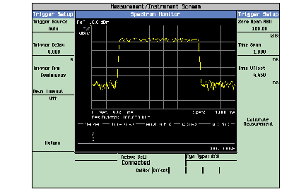
A typical zero span mode spectrum monitor display showing a bursted signal. The viewing window has been adjusted to zoom in on a single burst.
If the temperature of the test set drifts outside the calibrated temperature range of the spectrum monitor, a Measurement Uncalibrated message is displayed. To calibrate the spectrum monitor for the current temperature, press the Calibrate Measurement ( F11 ) key on the Trigger Setup menu.