How Do I Use the Spectrum Monitor?
Last updated: January 15, 2009
The following procedure shows a typical usage of the spectrum monitor in each of its two modes of operation; Swept Mode and Zero Span mode.
-
Establish a call with the mobile.
The spectrum monitor can also be used with any of the test set's test mode operating modes.NOTE
- Press the Instrument selection key.
- Select
Spectrum Monitor.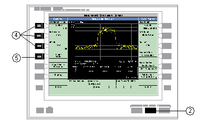
The spectrum monitor is displayed with the default settings as shown above. The center frequency is initially set at the expected frequency maintained by the test set's base station emulator. The
Swap Window Positions (
F5
)
key is only displayed when other measurements are active at the same time as the spectrum monitor.- Set the axis control as needed for your testing situation using the
Frequency Span (
F1
),
Reference ( F2 ), anddB/div ( F3 )keys. See Frequency Span, Resolution Bandwidth and Dynamic Range for the valid Frequency Span entries. To set the reference level manually (Autois the default), press the Reference ( F2) key then use the DATA ENTRY keys to enter the value you want.- Press the
Trigger Setup (
F4
)
key to access theTrigger Setupmenu.- Set the trigger settings to meet your testing needs. For example:
-
If you want the Spectrum Monitor to sweep immediately and continuously, ensure that
Trigger Arm (
F3
)
is set toContinuous. -
If you want to use external triggering, so that the Spectrum Monitor is triggered from a signal applied to the TRIG IN connector on the test set's rear panel, set
Trigger Source ( F1 )toExternal. - Trigger Delay ( F2 ) allows you to specify the point, relative to the trigger event where samples are taken (a negative trigger delay value collects pre-trigger samples). The same trigger delay setting is used for swept mode and zero span mode.
-
Res Bwallows you to set the resolution bandwidth. If you want the resolution bandwidth coupled with the with theFrequency Span, set this field toAUTOby pressing the gray DATA ENTRY softkey labeled ON , otherwise use the knob or the numeric DATA ENTRY soft keys to set the resolution bandwidth. See Frequency Span, Resolution Bandwidth and Dynamic Range to find the valid entries for the resolution bandwidth while in swept mode. Note that changing the resolution bandwidth does not modify the zero span resolution bandwidth setting.
- Press the
Return (
F6
)
key to exit theTrigger Setupmenu.- Press the
Display (
F6
)
key to access the display settings.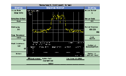
A typical spectrum monitor trace display is shown above. In this case, the
Displaymenu is open allowing you to access all of the display control settings using the ( F1 ) through ( F12 ) keys.The following list provides examples of some of the settings you may want to adjust:
-
Detection Method( F2 ) determines the algorithm used to find the value that represents each frequency bin. See Detection Method for more information. -
Peak Threshold( F4 ) andPeak Excursion( F5 ) set the peak threshold and peak excursion levels respectively. A peak is identified by using the peak threshold and peak excursion value. A point is only marked as a peak if it rises and falls more than the peak excursion value from the peak threshold value. -
Marker Mode( F8 ) sets the mode of the active marker.Positionmode activates a single frequency marker.Deltamode freezes the active marker at its current location and uses it as a reference marker. A second marker is created at the position of the reference marker and is used as a delta marker, reporting any change in amplitude or frequency from that of the reference marker. -
Peak Search( F10 ) moves the active marker to the highest peak on the spectrum monitor display, returning the numeric amplitude and frequency values. -
Marker -> Expected Freq( F11 ) sets the base station emulator's expected frequency to the frequency of the active marker. -
Marker -> Expected Power( F12 ) sets the base station emulator's expected power level to the amplitude of the active marker.
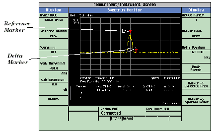
A typical swept mode spectrum monitor display is shown above. In this case, the active marker is marker 1, which is set to Delta mode.
- Press the
Return (
F6
)
key to exit theDisplaymenu.- To set the spectrum monitor to zero span mode, press the
Frequency Span (
F1
)
key and use the numeric DATA ENTRY keys to enter a value of0 MHz, or use the down-arrow key to reduce the span to zero.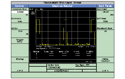
A typical zero span mode spectrum monitor display is shown above. Like swept mode, the Y-axis represents absolute amplitude. However, the X-axis now represents time rather than frequency.
- Press the
Trigger Setup (
F6
)
key. In zero span mode, additional trigger setup controls are available to you:-
If you want to change the view window over which you are looking at the signal, use the
Time Span ( F8 )andTime Offset ( F9 )keys. The measurement is made for the duration of the time span, beginning at the time defined by the trigger event plus the trigger delay plus the time offset. -
If you want to change the resolution bandwidth, press the
Zero Span RBW (
F7
)
key and select a value. (To measure the total power of a signal you must select a resolution bandwidth greater than or equal to the signal bandwidth.) See Frequency Span, Resolution Bandwidth and Dynamic Range to find the valid entries for the resolution bandwidth while in zero span mode. Note that changing the zero span resolution bandwidth does not modify the swept mode resolution bandwidth.
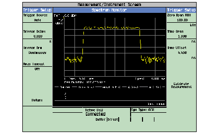
A typical zero span mode spectrum monitor display showing a bursted signal. The viewing window has been adjusted to zoom in on a single burst.
If the temperature of the test set drifts outside the calibrated temperature range of the spectrum monitor, a
Measurement Uncalibratedmessage is displayed. To calibrate the spectrum monitor for the current temperature, press the Calibrate Measurement ( F11 ) key on theTrigger Setupmenu.