Applying Cycle Sequences
Cycle Sequence Description
Create a Cycle Sequence
Export a Cycle Sequence
The Advanced Battery Test and Emulation application lets you create and import current-drain waveforms into the emulation to replicate real-life current drain scenarios that cell phone, laptop, or other battery types are subject to. Current drain waveforms can be created with a duration of up to 5.4 hours.
IMPORTANT: When using the N6705 DC Power Analyzer or the N6700 Modular Power System, you can only run cycle sequences on one of the installed power modules at a time. Single-output power supplies can run cycle sequences concurrently.
Cycle Sequence Description
Click + New Sequenceto create a battery cycle sequence. This action displays the Edit Battery Sequence dialog. The link below shows the Edit Battery Sequence dialog.
Click Load Sequence - to load an existing battery cycle sequence. Select the directory where the sequence is located.

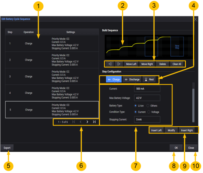
1. Sequence List - this area lists all of the steps in the cycle sequence. Steps
2. Build Sequence - indicates the area where the steps will be added in the sequence.
3. Move Left, Move Right buttons - move the highlighted waveform to the left or right.
Delete, Clear All buttons - delete the highlighted waveform, or clear all of the waveforms.
4. Step Configuration - select the step function (charge, discharge, or rest) in this area.
5. Export - exports the sequence file.
6. Navigation menu - use these controls to scroll through the sequence steps.
7. Configuration details - lets you provide configuration details for the selected step.
8. OK - applies the sequence to the battery cycle operation
9. Insert menu - select Modify to apply the edits to the step. Select Insert Left or Insert Right
to insert the step next to the highlighted step (waveform) in the Build Waveform area.
10. Close - closes and exits the Edit Battery Sequence dialog.
Create a Cycle Sequence
The following steps create a sequence consisting of a discharge, rest, and charge step.
Step 1. Specify the Discharge Step
In the Step Configuration area in the center of the window, select the Discharge step.
Make the following selections for the Discharge Mode: select Current, Constant Current, 100 mA.
Then specify the Max Battery Voltage and Cut-off Voltage.
Then select Insert Left. This places the Discharge step as the first step in the sequence.
![]()
The following describes the additional discharge mode selections:
Constant Current - specify the steady-state discharge current.
Dynamic - lets you configure a dynamic discharge current waveform. There are two options for specifying dynamic currents:
1. Configuring a new CD (constant dwell) waveform (see Create a CD Arb Waveform, or
2. Importing an existing waveform file that has been created from the CD ARB waveform editor, or importing a current waveform that was created from a BV9200B output list editor (see Load a Current Waveform File).
Edit Waveform - When CD Arb Waveform is selected, opens the Edit Waveform dialog, which lets you configure a CD Arb waveform.
Sequence Count - lets you specify a repeat count for the waveform, or specify Continuous repeat.
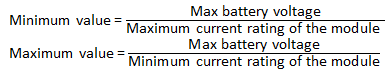
Constant Power - specify the steady-state discharge power. The default value is 0 W. The range is from 0 W – the module's (maximum current rating) x (cut-off voltage).
Constant Resistance - specify the steady-state discharge resistance. The default is the maximum value.
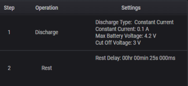
Step 2. Specify the Rest Step
In the Step Configuration area in the center of the window, select the Rest step.
Enter values for the rest Period. The minimum rest time is 1 millisecond; the maximum rest time is 1 day (86400 seconds). The instrument current and voltage limit are set to zero A, and maximum voltage respectively.
Then select Insert Left. This places the Rest step as the second step in the sequence.
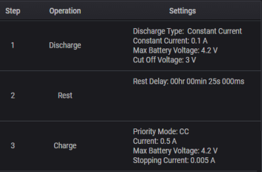
Step 3. Specify the Charge Step
In the Step Configuration area in the center of the window, select the Charge step. Select the Charging Mode (CC). Enter values for the charging Current, the Max Battery Voltage the Battery Type (Li=Ion), the Condition Type, and the Stopping Current.
If you are programing a CV charge step you will need to specify the Charging Voltage and the Current limit (in place of the charging Current and Max Battery Voltage).
Then select Insert Left. This places the Discharge step as the third step in the sequence.
Select Apply Waveform to apply the waveform to the opened Profile.
The following describes the Others Battery Type selections:
Battery Type - Others
You must select at least one of the following three cut-off conditions.
Time - specify the elapsed time after which the charge operation will stop. A drop-down menu lets you specify the cut-off time in seconds, minutes, hours, or days.
NDV - the negative delta value (NDV) specifies the maximum negative voltage drop that stops the charging operation.
Temperature - enter the temperature limit that stops the charging operation. Specify either Celsius or Fahrenheit in the dropdown. The default value is 25°C, with a range from 0°C to 100°C (32°F – 212°F).
The following selections are only available if Temperature has been checked, and if there is DAQ connected to the application.
Select DAQ - select any connected DAQ instrument to perform temperature measurements.
Select Slot - select any available DAQ slot where a temperature sensor is connected to measure ambient temperature.
Channel Number - select any DAQ Channel Number that has a temperature sensor connected to measure ambient temperature. You cannot select the DAQ channel number as an Output channel.
Temperature Sensor - select either Thermocouple or Thermistor temperature sensor.
Thermocouple Type - specify the thermocouple type from the dropdown list.
Step 4. Apply the Sequence
Select OK to apply the battery cycle function. The following figure shows the what appears on the display when the sequence is run.
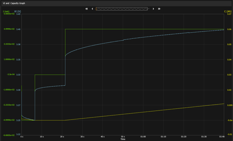
The display shows the three sequence steps: discharge, rest, and charging. The graph displays the current (I) and voltage V) values on the left side of the graph, and the Capacity values in Ah on the right side of the graph.
Export the Cycle Sequence
To export the cycle sequence:
Step 1. Click on the Export button in the lower left of the Edit Battery Sequence dialog to export the sequence file.
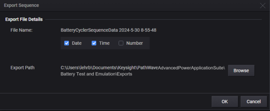
Step 2. Under Export File Details accept the default export path, or select Browse to specify a different location where you will save the file. Additionally, you can specify the item to append to the filename (date, time, or file number). Sequence files have the file extension .json.
Step 3. Select OK. After the sequence has been saved, a message will indicate that the sequence was successfully saved to the specified location.