Setup Sweep - Output Signal
Sweep Function
This sweep function generates voltage or current waveforms. The waveform can be varied by configuring the following sweep parameters:
| CONST (Constant) | Each step outputs constant voltage or current. |
| VAR1 (Primary Sweep) |
Each step outputs the VAR1 step number, dependent on voltage or current.
VAR1 sweep is repeated [VAR2 count * Repeat count] times. |
| VAR2 (Secondary Sweep) |
Each step outputs the VAR2 step number, dependent on voltage or current.
VAR2 step number increments with each VAR1 sweep. VAR2 sweep is repeated Repeat count times. |
| OPEN | Opens the output relay. |
| IGNORE | Does nothing. |
An example of the CONST/VAR1/VAR2/OPEN/IGNORE output signal is shown below. Note that the VAR1 count = 11, and the VAR2 count = 3.


Shape Function
Set the following parameters to configure a DC/Pulse shape waveform.
| DC | Outputs DC voltage or current after a Force Delay.
|
| Pulse | Outputs voltage or current pulse after a Force Delay. |
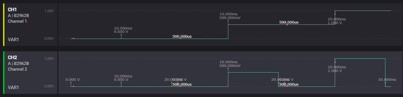
An example of the DC/Pulse Shape output signal is shown below. Note that the Source Delay = 10ms. and the Pulse Width = 10ms.
Linear/Log/List Function
Set the following parameters to sweep a Linear Single/Linear Double/Log Single/Log Double/List.
| Linear Single | The Linear step output from the Start to Stop value. |
| Linear Double
|
The Linear step output from the Start-to-Stop value and Stop-to-Start value. Each stair consists of [VARn Count / 2] steps. If VARn Count is odd, the Start-to-Stop value stair will consist of [(VARn Count + 1) / 2] steps, and the Stop-to-Start value stair will consist of [(VARn Count - 1) / 2] steps. |
| Log Single | The Logarithm step output from the Start-to-Stop value.
[Start * Stop] should be greater than zero.
|
| Log Double | The Logarithm step output from the Start-to-Stop value and Stop-to-Start value. Each stair consist of [VARn Count / 2] steps. If VARn Count is odd, the Start-to-Stop value stair will consist of [(VARn Count + 1) / 2] steps, and the Stop-to-Start value stair will consist of [(VARn Count - 1) / 2] steps. [Start * Stop] should be greater than zero. |
| List | Each step outputs in order to the user-specified voltage or current list. Lists the data array generate/edit in the List Edit Window. . |
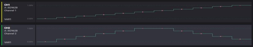
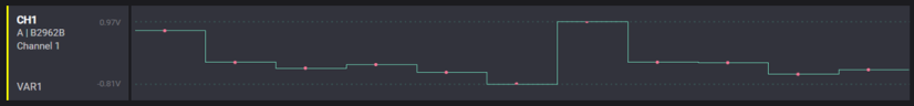
An example of a Linear Single/Linear Double output signal is shown below. Note that VAR1 Count = 11)
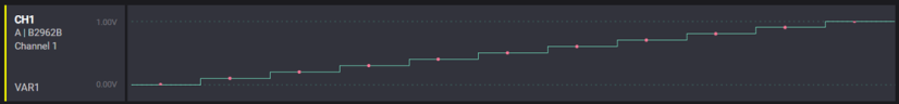
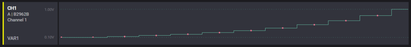
An example of a Linear Single/Logarithm Single/List output signal is shown below. Note that the List array data consists of random values.
Output Measurements
The sweep measurement function can measure voltage and/or current at each step.
Measurement Parameters
| Voltage | You can enable/disable voltage measurement as Channel Setting. The Voltage data name is displayed as "Voltage" in the Table/Graph view. |
| Current | You can enable/disable current measurement as Channel Setting. The Current data name is displayed as "Current" in the Table/Graph view. |
| Resistance | If both voltage and current measurements are enabled, the Resistance value is calculated as [voltage/current]. The Resistance data name is displayed as "Resistance" in the Table/Graph view. |
| Power | If both voltage and current measurements are enabled, the Power value is calculated as [voltage*current]. The Power data name is displayed as "Power" in the Table/Graph view. |
| Timestamp | Timestamp value indicates the measurement start time. The Timestamp timer is set to 0.0sec at the start of measurement. If either of voltage or current measurement is enabled, the Timestamp value data will be enabled. The Timestamp data name is displayed as "Time" in the Table/Graph view. |
| State | State value indicates the measurement status. The State data is only displayed on the Table view. If either a voltage or current measurement is enabled, the State value data will be enabled. The State data name is displayed as "State" in the Table view. |
| Source | Source value indicates the source voltage or current value. If the shape setting is Pulse, the Source data will be an invalid value. If either of voltage or current measurement is enabled, the Source value data will be enabled. The Source data name is displayed as "Source" in the Table/Graph view. |
Measurement Timing
If voltage or current measurement is enabled, measurement is performed at each step after the Measure Delay time.
Sweep Timing
The sweep measurement function can measure voltage and/or current at each step. Sweep measurements are affected by trigger mode as follows:
| Trigger Mode: Auto | Automatically adjust the step period. Force Delay, Measure Delay, Aperture Time, and Measure Range parameter settings affect the step period. In Auto mode, the step period is automatically selected from the latest step time of all controlled channels. For Multi-Frame channels control, the step time overhead will exceed 20ms for each step synchronisation. To speed up the process, consider using the Timer mode. |
| Trigger Mode: Timer | Fixed step periods. Each step period is fixed as much as possible. The actual step period may be greater than specified period depending on the parameter settings. If the step period is increased, multi channel steps will have different timings. Under the Timer mode, the period time should be longer than the longest step period. |