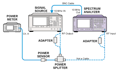
The slopes for each attenuator setting in DC Coupled mode, and in the 10 dB AC Coupled mode, are calculated and are stored in an array in EEROM on the A13 Front End Driver assembly. The test is performed at 50 MHz, 2.8 GHz, 6 GHz, 10 GHz, 15 GHz, and 20 GHz for the E4440A, up through 10 GHz for E4445A, up through 6 GHz for E4443A, and up through 40 GHz for E4446A/E4447A/E4448A. At each test frequency, source power level is set so that the power meter reads -10 dBm with the PSA set at 10 dB, DC Coupled attenuation. This value is then used as the reference for the other attenuator states at that frequency.
Instrument covers do not need to be removed for this adjustment. Also, this adjustment must only be performed if the PSA has valid flatness correction data.
This adjustment should be performed after replacing the A13 Front End Driver, or after replacing the A14 and/or A15 step attenuators.
|
Test Equipment |
Model Number |
E4440A |
E4446A |
|---|---|---|---|
|
Synthesized Sweeper |
PSG Models |
X |
X |
|
Power Meter |
N1914B |
X |
X |
|
Power Sensor |
N8485A |
X |
|
|
Power Sensor |
N8487A |
|
X |
|
Power Splitter |
11667C |
|
X |
|
Power Splitter |
11667B |
X |
|
|
BNC Cable |
8120-2582 |
X |
X |
|
2.4 mm Cable |
8120-6164 |
|
X |
|
3.5 mm Cable |
8120-4921 |
X |
|
|
3.5 mm (f) to 3.5 mm (f) adapter |
83059B |
X |
|
|
Type N (m) to 3.5 mm (m) adapter |
1250-1743 |
X |
|
|
2.4 mm (f) to 3.5 mm (f) adapter |
11901B |
X |
|
|
2.4 mm (f) to Type N (m) adapter |
11903D |
|
X |
|
3.5 mm (f) to Type N (m) |
08485-60005 |
X |
|
|
2.4 mm (f) to Type N (m) |
08487-60001 |
|
X |


