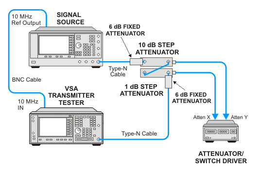
The Amplitude Linearity test verifies that the instrument meets the Amplitude Accuracy specification. In this test, a 50 MHz signal is passed through calibrated step attenuators to the E4406A VSA. In order to reduce mismatch errors, 6 dB pads are connected to either side of the step attenuators. With the source amplitude set to +10 dBm and the step attenuators set to 0 dB, the signal is measured on the VSA and the measurement is established as the test reference reading. Next, the external attenuation is increased and a delta reading is made on the VSA. The difference between the known attenuator loss and the VSA reading is the Amplitude Linearity error.
This test has three portions. The first portion sets the input level to –2 dBm, the VSA ADC is set to Auto, and the external attenuator is stepped from 0 to 62 dB.
The second part sets the input level to –2 dBm, the VSA ADC is set to –6 dBm and the external attenuator is stepped from 0 to 62 dB.
The third part sets the input level to –12 dBm, the VSA ADC is set to Auto, and the external attenuator is stepped from 0 to 62 dB
Click here for troubleshooting.
Related adjustments: None
|
Test Equipment |
Recommended Model Number |
|---|---|
|
RF Source 2 |
E8257D |
|
10 dB step attenuator |
8496G Option 001, H50 |
|
1 dB step attenuator |
8494G Option 001, H50 |
|
6 dB fixed attenuator |
8491A Option 006 |
|
Attenuator driver |
11713B |
|
Attenuator interconnector kit |
11716A |
|
Cable, Type-N |
11500C |
|
Cable, BNC |
8120-2582 |
