
The Agilent Recommended Test Plan has become the Factory Recommended Test Plan. Refer to the Test System Variants section of Getting Started for more information.
|
|
The Agilent Recommended Test Plan has become the Factory Recommended Test Plan. Refer to the Test System Variants section of Getting Started for more information. |
This topic shows the equipment required to run the performance verification and adjustment tests. Some tests (for example Flatness) can use various model numbers of a particular equipment type. The Recommended Model will provide the best results. However, the Alternative Model is an acceptable substitute.
Not all of the listed test equipment needs to be connected to perform an individual test. To run a test, only the equipment specified for that test needs to be connected.
The validity of performance verification and adjustment measurements depend in part on the accuracy of the required test equipment. Verify proper calibration of test equipment before running tests with this software.
The following sections are included in this topic:
|
Test Equipment |
Recommended Model |
Alternative Model |
|
Sources |
||
|
RF Source 1 |
E8257D1 |
E8257C |
|
RF Source 2 |
E8257D1 |
E8257C |
|
RF Source 3
|
E4433B Option UND |
E4430B Option UND |
|
RF Source 4
|
8665B |
8665A |
|
RF Source 5
|
E8257D1 |
E8257C |
|
Secondary Source
|
33250A function generator |
E8257C/D |
|
Analyzers |
||
|
Network analyzer |
N5245B PNA-X |
N5241A/B N5232A/B N5222A/B N5230A/C |
|
Counters |
||
|
Frequency counter |
53230A |
53220A |
|
Meters and Power Sensors (See below for calibration service ordering guidelines.) |
||
|
Digital multimeter
|
3458A |
|
|
Power meter |
N1914A2 |
N1912A |
|
Power sensor
|
N8482A |
N8482A Option CFT |
|
Power sensor, low power
|
8481D |
|
|
Standards |
||
|
Frequency standard |
Microsemi 5071A |
5061B |
|
Attenuators |
||
|
10 dB |
8496G Option 001, H50 |
8496H Option 001, H50 |
|
1 dB |
8494G Option 001, H50 |
8494H Option 001, H50 |
|
Attenuator Interconnect Kit3 |
11716A |
|
|
Attenuator Driver |
11713B |
11713A |
|
6 dB
|
8491A Option 006 |
8491B Option 006 |
|
20 dB
|
8491A Option 020 |
|
|
30 dB
|
11708A |
|
|
Filters |
||
|
50 MHz Low Pass |
0955-0306 |
|
|
1.0001 GHz Notch |
Trilithic CFN-2-1000.1 |
|
|
Miscellaneous Devices |
||
|
50 Ω termination |
909A Option 012 |
|
|
Power splitter |
11667A |
|
|
Directional bridge |
86205A |
8721A |
|
Calibration kit, Type-N |
85054B |
85032A/B/C/D/E/F |
|
Cables |
||
|
Type-N
|
11500C |
|
|
BNC
|
8120-2582 |
10503A |
|
Adapters |
||
|
Type-N (f) to Type-N (f) |
1250-1472 |
|
|
Type-N (m) to Type-N (m) |
1250-1475 |
|
|
Type-N (f) to BNC (m) |
1250-1477 |
|
|
Type-N (m) to BNC (f) |
1250-1476 |
|
|
Type-N (m) to BNC (m) |
1250-1473 |
|
|
3.5 mm (f) to Type-N (f)
|
1250-1745 |
|
|
Type-N (f) to 2.4 mm (f)
|
11903B |
|
|
7 mm to Type-N (f) |
Included in cal kit |
|

E8257D with Options 1EA/1EU, 1E1, 007, and UNX or UNR or UNY can be used as RF Source #1, RF Source #2, and RF Source #5.
N1914A power meters with serial number prefix prior to MY53040007 require Service Note N1914A-07 which fixes a power supply ground loop. The ground loop injects noise into the measurement circuits which can cause unstable measurements at low (–30 dBm) power levels
The step attenuators should be permanently joined via the 11716A Interconnect Kit as shown in the diagram.
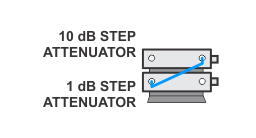
The step attenuator combination should have each attenuator setting characterized by a metrology lab at 50 MHz. The following tables show which sections of the 10 dB and 1 dB step attenuators are utilized for each attenuator setting. The tables also list the Allowable Uncertainty for each attenuator setting.
|
|
The interconnect cable should NEVER be disconnected once the loss characterization is performed. |
|
Nominal Attenuation |
Attenuator Section |
Recommended |
|||
|
#1 |
#2 |
#3 |
#4 |
||
|
0 |
Off |
Off |
Off |
Off |
0 (Reference) |
|
1 |
On |
Off |
Off |
Off |
< 0.005 |
|
2 |
Off |
On |
Off |
Off |
< 0.005 |
|
3 |
On |
On |
Off |
Off |
< 0.005 |
|
4 |
Off |
Off |
Ona |
Off |
< 0.005 |
|
5 |
On |
Off |
On |
Off |
< 0.005 |
|
6 |
Off |
On |
On |
Off |
< 0.005 |
|
7 |
On |
On |
On |
Off |
< 0.005 |
|
8 |
Off |
Off |
On |
On |
< 0.005 |
|
9 |
On |
Off |
On |
On |
< 0.005 |
|
10 |
Off |
On |
On |
On |
< 0.010 |
|
11 |
On |
On |
On |
On |
< 0.010 |
|
Nominal Attenuation |
Attenuator Section |
Recommended |
|||
|
#1 |
#2 |
#3 |
#4 |
||
|
0 |
Off |
Off |
Off |
Off |
0 (Reference) |
|
10 |
On |
Off |
Off |
Off |
< 0.010 |
|
20 |
Off |
On |
Off |
Off |
< 0.015 |
|
30 |
On |
On |
Off |
Off |
< 0.020 |
|
40 |
Off |
Off |
Ona |
Off |
< 0.025 |
|
50 |
On |
Off |
On |
Off |
< 0.030 |
|
60 |
Off |
On |
On |
Off |
< 0.035 |
|
70 |
On |
On |
On |
Off |
< 0.040 |
|
80 |
Off |
Off |
On |
On |
< 0.046 |
|
90 |
On |
Off |
On |
On |
< 0.055 |
|
100 |
Off |
On |
On |
On |
< 0.058 |
|
110 |
On |
On |
On |
On |
< 0.064 |
Use the following guidelines to ensure power sensors used by the N7800A application receive the correct calibration service:
Order Option 1A7 when ordering new power sensors that will be used as working standards in N7800A TME calibrations.
In the Americas region, order the Keysight Cal + Measurement Uncertainty for power sensor recalibration.
Outside the Americas region, order ISO 17025/ILAC-G8 calibration service for power sensor recalibration.
When ordering periodic calibration for instruments used as lab standards in the N7800A software, we recommend using “Keysight calibration + uncertainties” for power sensors, and “Keysight calibration + uncertainties + guardbanding” for all other items (please visit Selecting the Right Calibration Services). The N7800A software incorporates the ISO GUM Uncertainty in point-to-point uncertainty calculations. The special “H-series” calibration options in this table provide lower measurement uncertainties through use of direct comparison to devices directly characterized by NPL or NIST (or another NMI). Please order Option H99 to get data on a CD for easy import into the N7800A (avoids manual entry). The overall resulting N7800A measurement uncertainties then reflects these lower device uncertainties. The equipment requirements of each N7800A calibration application are summarized in the specials calibration matrix which can be found at the Recommended Lab Standards and Special Cal Options website.
The Keysight Option H99 is a special option for the Roseville Service Center [only] which provides a CD with calibration data included as a .csv file in TME N7800A format for all power sensors used with the N7800A TME application. N7800A TME is SSU calibration software used across Keysight SSU and by many self-maintainers. H99 must be requested from the Roseville SSU upon re-calibration only of any previously purchased power sensor and not for new purchases of BID Power Sensors. This option provides for adding the calibration data to a CD and may be ordered in addition to any other required or requested Std Lab Calibration option (must also be ordered in addition to H99). Option H99 is recommended but not required.
|
|
The following models are not supported by Option H99 (calibration data on a CD in .csv format):
|
The calibration and zeroing operation of a power sensor and power meter are done automatically by the software. Each operation is valid for 2 hours.
When a power sensor is needed for a given test, you will be asked to connect it to the appropriate power meter channel and POWER REF input in order to do the calibration and zeroing operation. The time stamp of the operation is then logged based on the serial numbers. The next time that a test requires the use of these two pieces of equipment, the last operation time stamp (if one exists) is checked to determine if a new calibration and zeroing operation is needed.
|
|
Disconnecting the power sensor from the channel port or powering down the power meter will invalidate a calibration and zeroing operation; closing the application will not. An existing logged time stamp will not be affected by these actions. |
A self -alignment procedure is automatically run when the E4406A VSA is turned on. The instrument will automatically run a new self-alignment procedure when 24 hours have elapsed.
When a test requires a self alignment, it will run it. The time stamp of the procedure is then logged based on the instrument serial number. When another test requires a self alignment, it first checks the last self-alignment time stamp to determine if a new procedure is needed.
|
|
Closing the application does not cause the deletion of the time stamp which is logged against the self alignment procedure. |
Please allow sufficient warmup time for the test equipment. Refer to the specified operating temperature range.
For test equipment, refer to individual operating and service manuals for warmup specifications.
To ensure data integrity for measurements carried out with TME (Test Management Environment), the following verification checks are carried out at the beginning of each test run. The checks are only performed on devices that require calibration data which directly affect the test results.
The following table lists the standard checks performed by default:
| Device | Parameter Name and Description | Limits | A Failure Affects: |
|---|---|---|---|
|
Noise Source |
NoiseRatio(dB)
|
Must be > and ≤ 30 at all points |
All tests runs |
|
Power Sensor |
CalFactor(%)
|
Must be ≥
10% and ≤
150% at all points. |
All test runs |
|
Uncertainty(%)
|
Must be > 0 and ≤ 3% at all points |
Test runs guard banded by measurement uncertainty only |
|
|
ReflectCoeff(Mag)
|
Must be > 0 and < 0.5 at all points |
Test runs guard banded by measurement uncertainty only |
|
|
Power Sensor |
LowBandCalFactor(%)
|
Same tests as for CalFactor(%) on a one-range power sensor |
All test runs |
|
HighBandCalFactor(%)
|
Same tests as for LowBandCalFactor(%) |
All test runs |
|
|
LowBandUncertainty(%)
|
Same tests as for Uncertainty(%) on a one-range power sensor |
Test runs guard banded by measurement uncertainty only |
|
|
HighBandUncertainty(%)
|
Same tests as for LowBandUncertainty(%) |
Test runs guard banded by measurement uncertainty only |
|
|
ReflectCoeff(Mag)
|
Same tests as for ReflectCoeff(Mag) on a one-range power sensor |
Test runs guard banded by measurement uncertainty only |
|
|
Step Attenuator |
Atten(dB)
|
Must be within 1 dB of the nominal attenuation. Must not all be exactly equal to the nominal attenuation (the default) at all points except zero. Zero step is the reference and must be zero. |
All test runs |
|
Uncert(dB)
|
Must be > 0 and ≤ 0.1 dB at all points except zero. Zero step is the reference and must be zero. |
Test runs guard banded by measurement uncertainty only |
|
|
ReflSize
|
Must be > 0 and < 0.5 at all points |
Test runs guard banded by measurement uncertainty only |
In addition to the standard checks carried out, the following additional limits affecting measurement uncertainty are verified for the E4406A VSA performance verification test plan.
|
|
Failure to comply with either set of limits will result in test data being labeled Invalid in both the TME interface and in any report produced from the data. |
|
Device |
Models |
Parameter
|
Frequency |
Limits |
A
Failure |
|
PowerSensor1 |
8482A |
Uncertainty(%) |
1 MHz – 4 GHz |
≤ 1.2 |
Test runs guard banded by measurement uncertainty only |
|
ReflectCoeff(Mag) |
7 MHz – 4 GHz |
≤ 0.130435 |
|
Device |
Models |
Parameter Name |
Attenuator Step |
Limits |
A
Failure |
|
StepAttenuator10-1 |
8496G |
Uncert(dB) |
0 |
= 0 |
Test runs guard banded by measurement uncertainty only |
|
10 |
≤ 0.0102 |
||||
|
20 |
≤ 0.0154 |
||||
|
30 |
≤ 0.0206 |
||||
|
40 |
≤ 0.0258 |
||||
|
50 |
≤ 0.031 |
||||
|
60 |
≤ 0.0362 |
||||
|
70 |
≤ 0.0414 |
||||
|
80 |
≤ 0.0466 |
||||
|
90 |
≤ 0.0518 |
||||
|
100 |
≤ 0.057 |
||||
|
110 |
≤ 0.0622 |
||||
|
ReflSize |
All |
≤ 0.0909091 |
|||
|
StepAttenuator1-1 |
8494G |
Uncert(dB) |
All except zero. Zero step is the reference and must be zero. |
≤ 0.01 |
|
|
ReflSize |
All |
≤ 0.0909091 |
