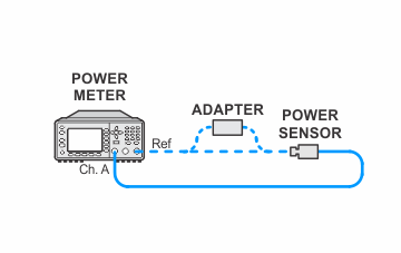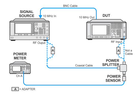
In the following setups, cables are designated as solid lines and direct connections are designated as dashed lines.
UXA — N9040B Options ≤ 526
This adjustment generates IF Flatness corrections for Options B25, B40, B85, B1A, and B1X. The amplitude corrections are relative to the center frequency of the IF. For Band 0 the only corrections that are generated are for Options B85, B1A, and B1X. These corrections are 58 overlapping segments from 140 MHz to 3.56 GHz in 60 MHz increments.
If the analyzer has Option MPB (Microwave Preselector Bypass), then corrections are generated in bands 1 through 6 for Options B25, B40, B85, B1A, and B1X. The corrections are single value corrections which are the average error of five measurements taken across the RF Band. Option MPB is necessary because the RF Preselector has approximately a 30 MHz bandwidth. The RF Preselector Bandwidth will band-limit the IF signal if it is in the path.
Click here for troubleshooting.
|
Test Equipment |
Recommended Model Number |
|---|---|
|
Microwave Signal Generator #1 |
PSG Models |
|
Power Meter |
N1914B |
|
Microwave Power Sensor
|
N8485A |
|
Microwave Power Splitter
|
11667B |
|
Millimeter Power Sensor
|
N8487A |
|
Millimeter Power Splitter
|
11667C |
|
Coaxial Cable, 3.5 mm (m) to 3.5 mm (m) |
11500F |
|
BNC Cable |
8120-1840 |
|
Type-N (m) to 3.5 mm (m) adapter |
1250-1743 |
|
3.5 mm (f) to 3.5 mm (f) adapter |
83059B |
|
3.5 mm (f) to 2.4 mm (f) adapter |
11901B |
|
3.5 mm (f) to Type-N (m) |
08485-60005 |
|
|
In the following setups, cables are designated as solid lines and direct connections are designated as dashed lines. |


