
This section lists the test equipment needed to run performance tests and adjustments. Models for each test equipment category are given in order of preference. Alternate models are also listed but should be considered a lower priority. Refer to each individual test for specific setup configurations with required cables and adapters.
|
Instrument |
Recommended Model1 |
Alternative Model1 |
Use2 |
|---|---|---|---|
|
Sources |
|||
|
Microwave
|
E8257D Options 567, 1EA/1EU, 1E1
|
PSG3 For Adjustments only:4
|
A, P, T |
|
Microwave
|
E8257D Opt 1EA/1EU |
PSG3 83630A/B/L4 Opt 001, 008 |
P |
|
Low
Noise
|
E8257D Options UNR, UNX, or UNY |
PSG3 Options UNR, UNX, or UNY |
A, P, T |
|
RF
Signal Generator
|
E8257D Options UNR, UNX, or UNY
|
PSG3 Options UNR, UNX, or UNY
|
A, P |
|
Ultra
Low Noise Source
|
Wenzel
Associates Inc
|
Model 500-13438 Rev C
|
P |
|
Function Generator |
33622A |
33612A
|
A, P |
|
Analyzers |
|||
|
Spectrum Analyzer
|
N9030B |
N9030A |
A, P |
|
Network Analyzer Used in adjustments for:
|
N5247B
|
N5247A/AS
|
A, U |
|
Audio Analyzer
|
U8903B |
Stanford Research Ultra Low Distortion Function Generator Model DS360 |
P |
|
Counters |
|||
|
Universal Counter |
53230A |
53132A |
A, P, T |
|
Meters and Power Sensors
|
|||
|
Digital Multimeter |
3458A |
34470A |
A, P, T |
|
Power Meter |
N1914B |
E4419A/B
|
A, P, U |
|
RF
Power Sensor, Type-N (m) connector
|
N8482A |
N8482A CFT (Non-H84 sensors will increase measurement uncertainty.) |
A, P |
|
RF
Power Sensor, Type-N (m) connector
|
E9304A Option H18 |
|
A, P |
|
Microwave
Power Sensor, 3.5 mm (m) connector
|
E9304A Option H20 |
|
A |
|
Microwave Power Sensor, 3.5 mm (m) connector
|
N8485A |
N8485A
CFT |
A, P |
|
Millimeter
Power Sensor, 2.4 mm (m) connector
|
N8487A-CFT |
N8487A |
A, P |
|
Millimeter Power Sensor 3, 2.4 mm (m) connector
|
N8487A |
N8488A |
A, U |
|
Millimeter Power Sensor 4, 1.85 mm (m) connector
|
N8488A |
None |
A, U |
|
Low Power Millimeter Power Sensor, 2.4 mm (m) connector
|
8487D |
|
A, P |
|
Low
Power Microwave Power Sensor, 3.5 mm (m) connector
|
8485D |
|
A, P |
|
USB
Power Sensor7, DC to 120 GHz, 1.0 mm (f) connector
|
U8489A Option 200 |
|
P |
|
75 Ω
Power Sensor, Type-N (m) connector
|
8483A |
|
P, A |
|
Power
Sensor Cable
|
11730A |
|
A, P, T |
|
Standards |
|||
|
Frequency Standard |
Microsemi 5071A-C002 |
HP/Agilent 5071A Option 001 10 MHz External Reference8 |
A, P |
|
50
MHz, |
Z5602B |
Z5602A |
A |
|
Attenuators |
|||
|
8496G Option 001, H50 |
8496H Option 001, H50 |
P |
|
|
8494G Option 001, H50 |
8494H Option 001, H50 |
P |
|
|
Attenuator
|
11716A |
|
P |
|
Attenuator Driver |
11713D |
11713E |
P |
|
3 dB |
8491A Option 003, H3311 |
8491B Option 003, H3311 |
P |
|
6 dB |
8490D Option 006 |
|
A, U |
|
6 dB |
8491A Option 006, H3311 |
8491B Option 006, H3311 |
P |
|
6 dB
|
8493C Option 006 |
|
A |
|
10 dB |
8491A Option 010, H3311 |
8491B Option 010, H3311 |
A, P |
|
10 dB |
8493C Option 010 |
|
A, P |
|
10 dB
|
8490D Option 010 |
|
P |
|
20 dB |
8491A Option 020 |
8491B Option 020 |
A, P |
|
20 dB
|
8493C Option 020 |
|
P |
|
30 dB
|
11708A |
|
A,P |
|
30 dB
|
Sage Millimeter STA-30-15-F2 |
|
P |
|
20 dB
|
Sage Millimeter STA-20-10-F2 |
|
P |
|
Terminations |
|||
|
Type-N (m)
|
909A Option 012 |
|
P, T |
|
3.5 mm (f)
|
909D |
|
P, T |
|
2.4 mm (f)
|
85138B |
901D |
A, P, T |
|
BNC (m)
|
1250-0207 |
11593A |
A, P, T |
|
Miscellaneous Devices |
|||
|
RF Power Splitter, Type-N (f) connector |
11667A |
|
A, P |
|
Microwave
|
11667B |
|
A, P |
|
Millimeter
|
11667C |
|
A, P |
|
Directional Bridge, Type-N (f) connector |
86205A |
|
P |
|
Directional Coupler, SMA (f) connector |
87300C |
|
P |
|
Millimeter Directional Coupler, 2.4 mm (f) connector
|
87301C |
|
P |
|
Microwave
|
11636B |
|
A, P |
|
Hybrid Power Divider, 3.5 mm (f) connector |
87302C |
|
A |
|
Comb Generator
|
U9391G Option FFM |
|
A, U |
|
DC Power Supply
|
U8001A |
|
A, U |
|
mmWave Signal Generator Frequency Extender,
|
E8257DV15 |
|
P |
|
mmWave Signal Generator Frequency Extender,
|
E8257DV10 |
|
P |
|
Minimum Loss Pad
|
11852B Option 401 |
|
A, P |
|
ECal module, 2.4 mm, 50 GHz |
N4693D Option M0F |
N4693A Option M0F (N4693-60001) |
U |
|
Cables |
|||
|
3.5 mm (m) to 3.5 mm (m) coaxial cable
|
11500E |
8120-4921 |
A, P |
|
3.5 mm (m) to 3.5 mm (m) coaxial cable |
11500F |
|
A, P |
|
2.4 mm (f) to 2.4 mm (m) cable
|
8120-6164 |
|
A, P |
|
2.4 mm (f) to 2.4 mm (m) cable
|
8121-2065 (or equivalent) |
|
A, P |
|
1 mm (f) to 1 mm (m) cable
|
11500J |
|
P |
|
Type-N, Precision Type-N (m) both ends
|
11500C |
11500B
|
A, P, T |
|
Type-N, Precision Type-N (m) both ends
|
N6314A |
|
A |
|
BNC, 50 Ω Coax BNC (m) both ends
|
8120-1840 |
8120-2582 |
A, P, T |
|
Cable Assembly, banana plugs
|
U9391-20013 |
|
A, U |
|
Filters |
|||
|
50 MHz Low Pass, BNC (m) to BNC (f)
|
Telonic Berkeley TLA 50-5AB2 |
0955-0306 |
P, T |
|
300 MHz Low Pass, BNC (m) to BNC (f)
|
Telonic Berkeley TLP 300-4AB4 |
0955-0455 |
P |
|
1.8
GHz Low Pass, SMA (f) to SMA (f)
|
RLC L-1636 |
0955-0491 |
P |
|
5.0 GHz Low Pass, SMA (f) to SMA (f) |
RLC F-30-5000-RF |
|
P |
|
8.0 GHz Low Pass, SMA (f) to SMA (f) |
RLC F-30-8000-RF |
|
P |
|
12.4 GHz Low Pass, SMA (f) to SMA (f) |
RLC F-30-12.4-RF |
|
P |
|
1 GHz Notch Filter
|
Trilithic CFN-2-1000.1 |
|
P |
|
Adapters |
|||
|
Type-N (f) to Type-N (f) |
1250-1472 |
|
P |
|
Type-N (m) to Type-N (m) |
1250-1475 |
|
P |
|
Type-N (m) (50 Ω) to Type-N (f) (75 Ω)
|
1250-0597 |
|
A, P |
|
Type-N (f) (75 Ω) to Type-N (f) (75 Ω)
|
Huber + Suhner 31_N-75-0-2 /133_NE |
|
A, P |
|
Type-N (f) to BNC (m) |
1250-1477 |
|
P, T |
|
Type-N (m) to BNC (m) |
1250-1473 |
|
P, T |
|
Type-N (m) to BNC (f) |
1250-1476 |
|
P |
|
Type-N (m) to 3.5 mm (m) |
1250-1743 |
|
|
|
Type-N (m) to 3.5 mm (f)
|
1250-1744 |
|
|
|
Type-N (f) to 3.5 mm (f)
|
1250-1745 |
|
|
|
Type-N (f) to 3.5 mm (m) |
1250-1750 |
|
|
|
3.5 mm (f) to 3.5mm (f)
|
83059B |
1250-1749 |
P |
|
3.5 mm (m) to 3.5 mm (m)
|
83059A |
1250-1748 |
P |
|
3.5 mm (m) to 3.5 mm (f) |
83059C |
|
P |
|
3.5 mm (f) to 2.4 mm (f)
|
11901B |
|
|
|
2.4 mm (f) to 2.4 mm (f)
|
11900B |
|
P |
|
2.4 mm (f) to 3.5 mm (m) |
11901D |
|
A, P |
|
2.4 mm (m) to 3.5 mm (f) |
11901C |
|
A |
|
Type-N (f) to 2.4 mm (f)
|
11903B |
|
A, P |
|
Type-N (f) to 2.4 mm (m)
|
11903C |
|
P |
|
Type-N (m) to 2.4 mm (f)
|
11903D |
|
P |
|
2.4 mm (f) to 2.92 mm (f)
|
11904B |
|
P, A |
|
2.4 mm (m) to 2.92 mm (f)
|
11904C |
|
P, A |
|
2.4 mm (m) Aeroflex Weinschel Crown
|
7005A-13 |
|
P, A |
|
1 mm ruggedized (f) to 2.4 mm (f) adapter
|
5067-6655 |
|
P |
|
W-Band Waveguide to 1 mm adapter
|
Sage Millimeter SWC-101F-E1 |
|
P |
|
V-Band Waveguide to 1 mm adapter
|
Sage Millimeter SWC-151F-E1 |
|
P |
|
BNC (m) to SMA (f) |
1250-1700 |
|
P |
|
BNC Tee (BNC f,m,f) |
1250-0781 |
|
A, P |
|
BNC (f) to SMA (m) |
1250-1200 |
|
A, P |
|
BNC (f) to Dual Banana |
1251-2277 |
|
A, P |
|
1 mm (f) to 2.4 mm (f) adapter
|
11922B |
|
P |
|
3.5 mm (f) to Type-N (m)
|
08485-60005 |
|
A, P |
|
2.4 mm (f) to Type-N (m)
|
08487-60001 |
|
A, P |
|
Type-N Tee |
1250-0559 |
|
P |
|
Optional Equipment |
|||
|
10 MHz Distribution Amplifier
|
Microsemi 5087B |
5087A |
A, P |
Keysight, Agilent, or Hewlett-Packard model numbers unless otherwise noted.
A = Adjustments, P = Performance Testing, T = Troubleshooting
E8267D
|
|
|
The (obsolete) 836xxA/B/L synthesized generators are only allowed in the following applications:
|
Mapped As |
Performance |
Adjustments | Utilities |
|
Signal Generator |
No |
Yes |
No |
|
Signal Generator |
Yes |
Yes |
No |
N1914A power meters with serial number prefix prior to MY53040007 require Service Note N1914A-07 which fixes a power supply ground loop. The ground loop injects noise into the measurement circuits which can cause unstable measurements at low (-30 dBm) power levels.
The 8482A power sensor uses cal factors to compensate the power sensor for frequency response errors. Cal factors are stated in percentages. The 8482A factory cal factor uncertainty ranges from 2.2% to 3.1%. The cal factor uncertainty can be reduced to < 1.0% by using metrology grade calibration techniques. The power sensor cal factor uncertainty becomes one component of the Verification Test uncertainty analysis. Lower cal factor uncertainties will translate to wider test margins.
The table below shows the various options that will provide USB ports on the N1914A power meter. Note that the N1914B power meter comes standard with USB ports.
|
N1914A Orderable Options |
Description |
FW responds as option1 |
|
|
201 |
Ordered from the factory with new N1914A |
Dual channel average power meter with VGA, trigger in/out, 1 front and 1 rear USB port |
008, 010, 012 |
|
The following options are ordered as upgrades to an existing N1914A power meter. |
|||
|
106 |
This is the recommended option. |
Dual channel average power meter with 1 front and 1 rear USB port |
008 |
|
103 |
alternate |
Dual channel average power meter, battery, 2 rear USB ports |
001, 009 |
|
105 |
alternate |
Dual channel average power meter with VGA, battery, 1 front and 1 rear USB port |
008, 010 |
|
108 |
alternate |
Parallel rear-panel sensor input connectors, front-panel reference calibrator connector, 2 rear USB ports |
002, 009 |
|
109 |
alternate |
Parallel rear-panel sensor input connectors, rear-panel reference calibrator connector, 2 rear USB ports |
003, 009 |
|
111 |
alternate |
Dual channel average power meter, battery, 1 front and 1 rear USB port |
001, 008 |
|
167 |
alternate |
Dual channel average power meter, external trigger in/out, 1 front and 1 rear USB port |
008, 012 |
|
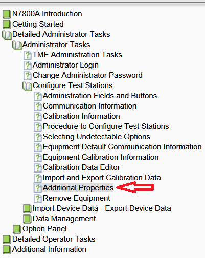
When using the 10 MHz External Reference (for performance tests), be sure to update the Additional Properties in TME to the correct Frequency Accuracy in parts per million (ppm). For example, if overall accuracy is 9e-12, the equivalent is 9e-6 ppm. Refer to the Additional Properties section in the N7800A TME Help for instructions.
The step attenuators should be permanently joined using the 11716A Interconnect Kit as shown in the diagram.
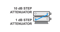
Step Attenuator Loss Characterization
The step attenuator combination should have each attenuator setting characterized by a metrology lab at 50 MHz. This characterization can be ordered through Keysight Technologies as an Option H50 Calibration.
The following tables show which sections of the 10 dB and 1 dB step attenuators are utilized for each attenuator setting. The tables also list the Recommended Uncertainty for each attenuator setting. A larger number will result in larger overall test uncertainties which could affect the test pass/fail rate.
|
|
The interconnect cable should NEVER be disconnected once the loss characterization is performed. |
|
Nominal Attenuation |
Attenuator Section |
Recommended Uncertainty |
|||
|
#1 |
#2 |
#3 |
#4 |
||
|
0 |
Off |
Off |
Off |
Off |
0 (Reference) |
|
1 |
On |
Off |
Off |
Off |
< 0.005 |
|
2 |
Off |
On |
Off |
Off |
< 0.005 |
|
3 |
On |
On |
Off |
Off |
< 0.005 |
|
4 |
Off |
Off |
Ona |
Off |
< 0.005 |
|
5 |
On |
Off |
On |
Off |
< 0.005 |
|
6 |
Off |
On |
On |
Off |
< 0.005 |
|
7 |
On |
On |
On |
Off |
< 0.005 |
|
8 |
Off |
Off |
On |
On |
< 0.005 |
|
9 |
On |
Off |
On |
On |
< 0.005 |
|
Nominal Attenuation |
Attenuator Section |
Recommended Uncertainty |
|||
|
#1 |
#2 |
#3 |
#4 |
||
|
0 |
Off |
Off |
Off |
Off |
0 (Reference) |
|
10 |
On |
Off |
Off |
Off |
< 0.010 |
|
20 |
Off |
On |
Off |
Off |
< 0.015 |
|
30 |
On |
On |
Off |
Off |
< 0.020 |
|
40 |
Off |
Off |
Ona |
Off |
< 0.025 |
|
50 |
On |
Off |
On |
Off |
< 0.030 |
|
60 |
Off |
On |
On |
Off |
< 0.035 |
|
70 |
On |
On |
On |
Off |
< 0.040 |
8491A Option H33 is a fixed attenuator which has been characterized to have a VSWR ≤ 1.05:1 at 50 MHz. A VSWR of 1.05:1 is recommended to test Input Attenuator Switching Uncertainty, Display Scale Fidelity, and Absolute Amplitude Accuracy performance tests. Any 8491A/B attenuator can be mapped into this device if the VSWR at 50 MHz has been characterized to be ≤ 1.05:1. When mapping the attenuator to indicate that it meets the required specification, the Option H33 checkbox will need to be checked in the configure test station Administration screen.
Use the following guidelines to ensure power sensors used by the N7800A application receive the correct calibration service:
Order Option 1A7 when ordering new power sensors that will be used as working standards in N7800A TME calibrations.
When ordering periodic calibration for instruments used as lab standards in the N7800A software, we recommend using “Keysight Cal + Uncertainties + Guardbanding”. More information can be found at http://www.keysight.com/find/americas_cal.
The N7800A software incorporates the ISO GUM Uncertainty in point-to-point uncertainty calculations. The special “H-series” calibration options (shown on the Special Calibrations Matrix located at http://cal.software.keysight.com) provide lower measurement uncertainties through use of direct comparison to devices directly characterized by NPL or NIST (or another NMI). The overall resulting N7800A measurement uncertainties then reflects these lower device uncertainties. The equipment requirements of each N7800A calibration application are summarized in the Special Calibrations Matrix which can be found at http://cal.software.keysight.com.
Option H99 is a special option for the Roseville Service Center [only] which provides electronic calibration data available as a .csv file that can be imported into TME thus avoiding manual entry. Option H99 must be requested from the Roseville Service Center upon re-calibration only of any previously purchased power sensor and not for new purchases of power sensors. This option may be ordered in addition to any other required or requested Std Lab Calibration option. Option H99 is recommended but not required.
|
|
The following models are not supported by Option H99:
|
To ensure data integrity for measurements carried out with TME (Test Management Environment), the following verification checks are carried out at the beginning of each test run. The checks are only performed on devices that require calibration data which directly affect the test results.
The following table lists the standard checks performed by default:
|
|
Failure to comply with the CalFactor(%) or Atten(dB) will result in test data being labeled Invalid in both the TME interface and in any report format produced from the data. |
| Device | Parameter Name and Description | Limits | A
Failure Affects: |
|---|---|---|---|
|
Noise Source |
NoiseRatio(dB)
|
Must be > 0 and ≤ 30 at all points |
All test runs |
|
Power Sensor |
CalFactor(%)
|
Must be ≥
10% and ≤
150% at all points. |
All test runs |
|
Uncertainty(%)
|
Must be > 0 and ≤ 10% at all points |
Test runs guard banded by measurement uncertainty only |
|
|
ReflectCoeff(Mag)
|
Must be > 0 and < 0.5 at all points |
Test runs guard banded by measurement uncertainty only |
|
|
Power Sensor |
LowBandCalFactor(%)
|
Same tests as for CalFactor(%) on a one-range power sensor |
All test runs |
|
HighBandCalFactor(%)
|
Same tests as for LowBandCalFactor(%) |
All test runs |
|
|
LowBandUncertainty(%)
|
Same tests as for Uncertainty(%) on a one-range power sensor |
Test runs guard banded by measurement uncertainty only |
|
|
HighBandUncertainty(%)
|
Same tests as for LowBandUncertainty(%) |
Test runs guard banded by measurement uncertainty only |
|
|
ReflectCoeff(Mag)
|
Same tests as for ReflectCoeff(Mag) on a one-range power sensor |
Test runs guard banded by measurement uncertainty only |
|
|
Step Attenuator |
Atten(dB)
|
Must be within 1 dB of the nominal attenuation.
|
All test runs |
|
Uncert(dB)
|
Must be > 0 and ≤ 0.1 dB at all points except zero. Zero step is the reference and must be zero. |
Test runs guard banded by measurement uncertainty only |
|
|
ReflSize
|
Must be > 0 and < 0.5 at all points |
Test runs guard banded by measurement uncertainty only |

