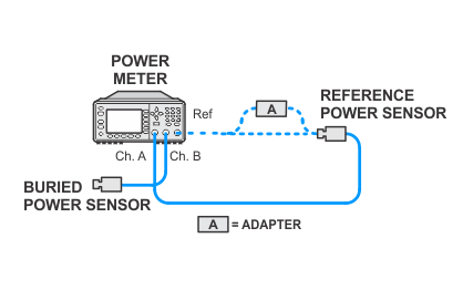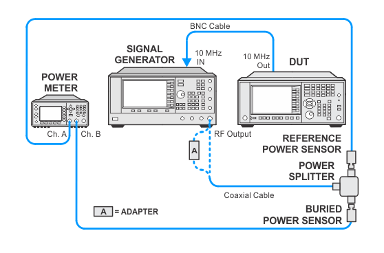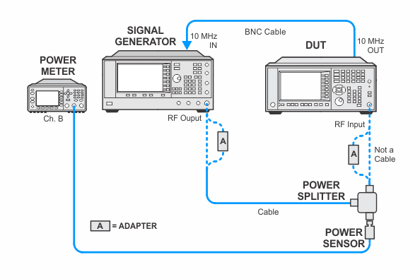
In the following setups, cables are designated as solid lines and direct connections are designated as dashed lines.
NFA — N8973B/74B/75B/76B
The attenuator slope adjustment is a rough flatness adjustment for attenuator settings other than 10 dB. The flatness adjustment is performed in 10 dB attenuation only. This adjustment is performed at various frequencies for each attenuator setting in DC-Coupled mode, and at 10 dB of attenuation in AC-Coupled mode for models that allow AC-Coupled mode.
The Total Flatness Correction for any RF Attenuator setting are managed as follows:
Total Flatness Correction = Reference Flatness Correction (generated with 10 dB attenuation) + Attenuator Slope Correction (relative to 10 dB Attenuation) + AC Coupling Correction (if AC Coupling is set)
This calibration should only be performed after replacing the RF attenuators or the front end assembly.
Click here for troubleshooting.
|
Test Equipment |
Recommended Model Number |
|---|---|
|
Microwave Signal Generator #1 |
PSG Models |
|
Power Meter |
N1914B |
|
Microwave Power Sensor
|
N8485A |
|
Microwave Power Splitter
|
11667B |
|
Millimeter Power Sensor
|
N8487A CFT |
|
Millimeter Power Splitter
|
11667C |
|
BNC Cable |
8120-1840 |
|
Coaxial Cable, 2.4 mm |
8120-6164 |
|
Coaxial Cable, 3.5 mm |
11500E |
|
3.5 mm (f) to 3.5 mm (f) adapter |
83059B |
|
Type N (m) to 3.5 mm (m) adapter |
1250-1743 |
|
2.4 mm (f) to 3.5 mm (f) adapter |
11901B |
|
3.5 mm (f) to Type N (m) adapter |
08485-60005 |
|
2.4 mm (f) to Type N (m) adapter |
08487-60001 |
|
|
In the following setups, cables are designated as solid lines and direct connections are designated as dashed lines. |


