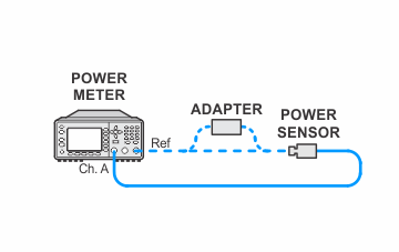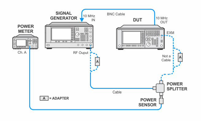
In the following setups, cables are designated as solid lines and direct connections are designated as dashed lines.
UXA — N9040B
This adjustment generates corrections for the External IF Input Gain. The basic algorithm inputs a –25 dBm signal into the External IF Input. The DUT is placed in external mixing mode, the corrections are turned off, and the signal amplitude is measured. The amplitude error is stored as a correction. The amplitude error is measured at various frequency offsets (from center frequency) across the IF Bandwidth. This adjustment is performed on the following IF Paths:
|
IF Path |
Bandwidth |
IF Frequency |
|
Standard |
10 MHz |
322.5 MHz |
|
Option B25 |
25 MHz |
322.5 MHz |
|
Option B40 |
40 MHz |
250.0 MHz |
|
Option B85 |
85 MHz |
300.0 MHz |
|
Option B1A |
125 MHz |
300.0 MHz |
|
Option B1X |
140 MHz |
300.0 MHz |
|
Option B2X |
255 MHz |
750.0 MHz |
|
Option B5X |
510 MHz |
877.1484375 MHz |
Click here for troubleshooting.
|
Test Equipment |
Recommended Model Number |
|---|---|
|
Microwave Signal Generator #1 |
PSG Models |
|
Power Meter |
N1914B |
|
Microwave Power Sensor |
N8485A |
|
Microwave Power Splitter |
11667B |
|
Coaxial Cable, 3.5 mm |
11500E |
|
BNC Cable |
8120-1840 |
|
3.5 mm (m) to 3.5 mm (m) adapter |
83059A |
|
3.5 mm (f) to 3.5 mm (f) adapter |
83059B |
|
2.4 mm (f) to 3.5 mm (f) adapter |
11901B |
|
3.5 mm (f) to Type-N (m) adapter |
08485-60005 |
|
|
In the following setups, cables are designated as solid lines and direct connections are designated as dashed lines. |


