The associated IF Phase Linearity Check is located under the Utilities Menu. It is recommended that the IF Phase Linearity Check Utility be performed after the IF Phase Linearity Adjustment is performed.
|
|
The associated IF Phase Linearity Check is located under the Utilities Menu. It is recommended that the IF Phase Linearity Check Utility be performed after the IF Phase Linearity Adjustment is performed. |
UXA — N9040B
With options:
FBP
This
If Option MPB (Preselector Bypass) is installed, the adjustment will be performed on band 1 through 6. Option FBP (Full Bypass Path) is the combination of both MPB and Option LNP (Low Noise Path). If Option FBP is installed, the
To summarize the Option MPB dependency:
|
Option MPB installed: |
Option B2X: Adjust for Bands 0, 1, 2, 3, 4, 5, 6 Option B5X: Adjust for Bands 0, 1, 2, 3, 4, 5, 6 |
|
Option MPB NOT installed: |
Option B2X: Adjust for band 0 only Option B5X: Adjust for band 0 only |
A comb generator outputs a series of comb teeth that start at 9.765625 MHz (or whatever the source frequency is chosen) and step in 9.765625 MHz increments to 50 GHz. The comb teeth are assumed to be phase coherent across the IF bandwidth of interest. The comb generator will output a burst of comb teeth, and the DUT will be triggered to perform a spectrum measurement. The trace will contain a series of bursts spaced in 0.1024 us (or 1/9.765625 MHz) steps. The phase angle of each individual comb tooth will be read from the DUT with the CALC:SPEC:MARK1:PHAS? command.
|
Band |
IF Path |
Span (MHz) |
Tone Space (MHz) |
Tone Count |
|
0 to 6 |
B2X |
253.90625 |
9.765625 |
27 |
|
0 to 4 |
B5X |
507.8125 |
9.765625 |
53 |
|
5, 6 |
B5X |
507.8125 |
19.53125 |
27 |
|
0 to 4 |
H1G |
996.09373 |
9.765625 |
103 |
|
5, 6 |
H1G |
996.09373 |
19.53125 |
52 |
This will result in an array that is phase angle (in radians) vs offset frequency. The phase angle will be wrapped such that an angle greater than Pi (radians) will be a negative angle. The negative phase angles will be converted to positive values, for instance –(Pi/2) will be converted to (3Pi)/2. The phase angles will be unwrapped by adding 2*Pi each time the angle crosses zero radians.
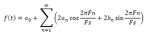
Once the phase angle has been unwrapped, a regression line will be calculated through the data. The phase for each comb tooth will be normalized to the regression line to generate the comb phase error. The Phase Response can be described by an Nth order Fourier series.
The an term is the real component, and the bn term is the imaginary component.
Where FS is the sampling frequency (300 MHz for B2X, or 600 MHz for B5X). Fn is the comb offset frequency. A matrix will be created with n = 10.
|
|
|
Click here for troubleshooting.
|
Test Equipment |
Recommended Model Number |
|
RF Signal Generator |
PSG Models |
|
Comb Generator |
U9391G Option FFM |
|
DC Power Supply |
U8001A |
|
Attenuator, 6 dB fixed |
8490D Option 006 |
|
Cable, 2.4 mm (m) to 2.4 mm (f) |
8120-6164 |
|
Cable, BNC (m) to BNC (m)
|
8120-1840 |
|
Cable assembly for connecting power supply to comb generator |
U9391-20013 |
|
Adapter, 2.4 mm (f) to 3.5 mm (m) |
11901D |
|
Adapter, 2.4 mm (f) to 3.5 mm (f)
|
11901B |
|
Adapter, Type-N (m) to 2.4 mm (f)
|
11903D |
|
Adapter, 2.4 mm (f) to 2.4 mm (f)
|
11900B |
|
Adapter, SMA (m) to BNC (f) |
1250-1200 |
|
|
|