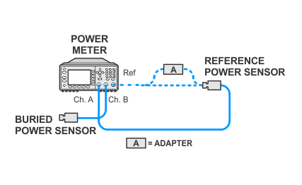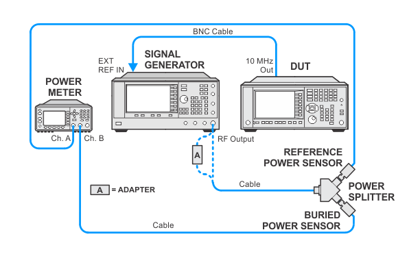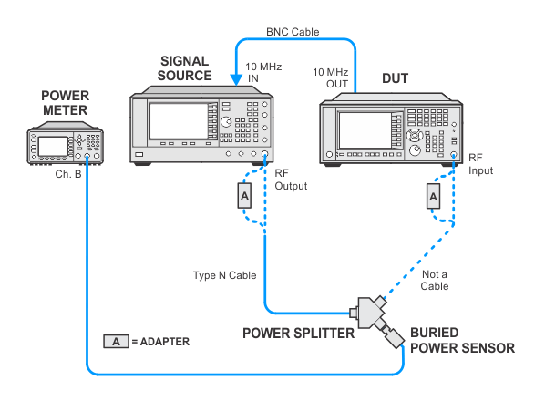
In the following setups, cables are designated as solid lines and direct connections are designated as dashed lines.
NFA — N8973B/74B/75B/76B
Frequency response (aka. Flatness) is defined as the amplitude deviation from the reference amplitude at 50 MHz. The complete analyzer frequency response is measured with several tests.
The model and options of the DUT will determine which tests are run from the list below.
A “buried power sensor” technique is used to characterize the tracking error of a power splitter in order to avoid the relatively large specified tracking error. This reduces the measurement uncertainty low enough to verify the frequency-response specification for the 300 kHz to 3.6 GHz range. Two buried sensor setups for preamp On/Off will be required to complete this test. The buried sensor calibration is valid for four hours.
AC-coupled Flatness is specified for 10 MHz to 26.5 GHz and is most critical at 10 MHz, where the DC Blocking Capacitor begins to roll-off. AC Coupled Flatness is not to be measured above 3.6 GHz in order to keep test times as short as possible.
Click here for troubleshooting.
|
Test Equipment |
Recommended Model Number |
|---|---|
|
RF Signal Generator |
PSG Models |
|
Power Meter |
N1914B |
|
RF Power Sensor |
N8482A |
|
RF Power Splitter |
11667A |
|
BNC Cable |
8120-1840 |
|
Type-N Cable |
11500C |
|
Type-N (m) to Type-N (m) adapter |
1250-1475 |
|
3.5 mm (f) to Type-N (f) adapter |
1250-1745 |
|
2.4 mm (f) to Type-N (f) adapter |
11903B |
|
|
In the following setups, cables are designated as solid lines and direct connections are designated as dashed lines. |


