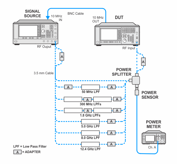
In the following setups, cables are designated as solid lines and direct connections are designated as dashed lines.
UXA — N9041B
At each test frequency a -15 dBm (-30 dBm for CXA) signal is applied to the mixer. One or more low pass filters are inserted between the source and the DUT to prevent the second harmonic of the source from artificially raising the second harmonic product as it is displayed on the DUT. The Marker Delta function is used to measure the level of the distortion product relative to the carrier. The Second Harmonic Intercept point (SHI) is calculated through the equation SHI = Mixer Level - Distortion.
Click here for troubleshooting.
|
Test Equipment |
Recommended Model Number |
|---|---|
|
Microwave Signal Generator #1 |
PSG Models |
|
Power Meter |
N1914B |
|
Microwave Power Sensor |
N8485A |
|
Microwave Power Splitter |
11667B |
|
50 MHz Low Pass Filter |
Telonic Berkeley TLA 50-5AB2 |
|
300 MHz Low Pass Filter |
Telonic Berkeley TLP 300-4AB4 |
|
1.8 GHz Low Pass Filter |
RLC L-1636 |
|
5.0 GHz Low Pass Filter |
RLC F-30-5000-RF |
|
8.0 GHz Low Pass Filter |
RLC F-30-8000-RF |
|
12.4 GHz Low Pass Filter |
RLC F-30-12.4-RF |
|
BNC Cable |
8120-1840 |
|
Coaxial Cable, 3.5 mm |
11500E |
|
3.5 mm (f) to 3.5 mm (f) adapter |
83059B |
|
2.4 mm (f) to 3.5 mm (f) adapter |
11901B |
|
BNC (m) to 3.5 mm (f) adapter |
1250-1250 |
|
3.5 mm (f) to Type-N (m) adapter |
08485-60005 |
|
3.5 mm (m) to 3.5 mm (m) |
1250-1748 |
|
BNC (f) to 3.5 mm (m) adapter |
1250-1200 |
|
Type-N (m) to 3.5 mm (m) adapter |
1250-1743 |
|
|
In the following setups, cables are designated as solid lines and direct connections are designated as dashed lines. |