UXA N9041B signal generators will run a separate test on RF Input 2.
All X-Series models
|
|
UXA N9041B signal generators will run a separate test on RF Input 2. |
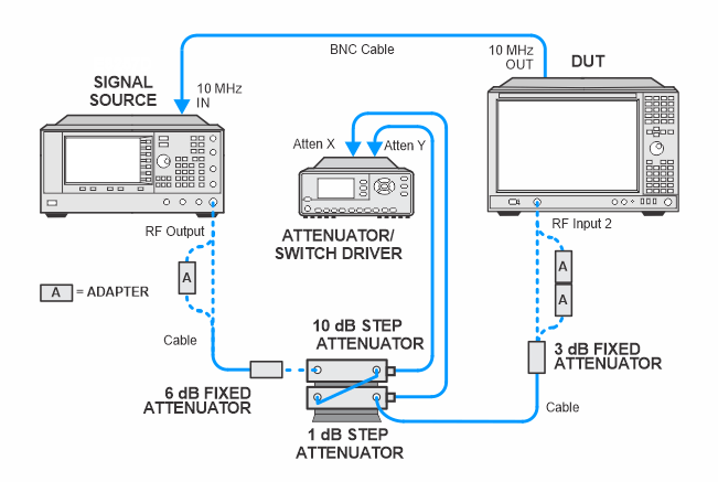
This test verifies the scale fidelity (linearity) of the analyzer at 50 MHz by comparing it to an external precision attenuator. As the external attenuation is increased in steps, the change in power level indicated by the analyzer's display-marker is monitored. This test is performed in two parts so the step attenuator uncertainties are minimized.
The analyzer input attenuator is set to 10 dB in zero-span mode. The source is set to +10 dBm and the external composite attenuator is set to 19 dB. The resulting –25 dBm signal is measured by the analyzer and recorded as the reference. The analyzer input power is then varied between –11 dBm and –17 dBm (–21 dBm to –27 dBm at the mixer) by switching the external attenuator.
The analyzer input attenuator is set to 10 dB in zero-span mode. The source is set to -10 dBm and the external composite attenuator is set to 19 dB. The resulting -25 dBm signal is measured by the analyzer and recorded as the reference. The input power is then varied between the -25 dBm and -75 dBm (-35 dBm to -85 dBm at the mixer) by switching the external attenuator.
|
|
At signals below -85 dBm, noise (not linearity) becomes the dominant error. Noise averaging would increase test times, so these levels are not measured. |
|
|
This test requires step attenuator calibration data to obtain valid results. Make sure you enter the calibration data for the step attenuators that you're using. Please refer to the Enter Equipment Calibration Data section in the TME help for details on how to enter this data. You must enter the data for the following columns to obtain valid results: Attn(dB), Uncert(dB) and ReflSize. |
Click here for troubleshooting.
|
Test Equipment |
Recommended Model Number |
|---|---|
|
Microwave Signal Generator #1 |
PSG Models |
|
1 dB Step Attenuator |
8494G Option 001, H50 |
|
10 dB Step Attenuator |
8496G Option 001, H50 |
|
Attenuator Driver |
11713D |
|
Attenuator Interconnect Kit |
11716A |
|
3 dB Fixed Attenuator |
8491A Option 003, H33 |
|
6 dB Fixed Attenuator |
8491A Option 006, H33 |
|
10 dB Fixed Attenuator |
8491A Option 010, H33 |
|
Type-N Cable |
11500C |
|
BNC Cable |
8120-1840 |
|
1 mm ruggedized (f) to 2.4 mm (f) adapter (for N9041B) |
5067-6655 |
|
2.4 mm (m) to Type-N (f) adapter |
11903C |
|
3.5 mm (f) to Type-N (f) adapter |
1250-1745 |
|
2.4 mm (f) to Type-N (f) adapter |
11903B |
|
|
In the following setups, cables are designated as solid lines and direct connections are designated as dashed lines. |