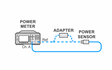
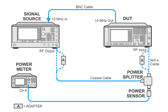
In the following setups, cables are designated as solid lines and direct connections are designated as dashed lines.
All X-Series models
This test verifies that the analyzer meets its specification for input related spurious responses. In this test, the source is connected to the RF Input and set for the spur frequency. The source amplitude is measured using a power meter. The source frequency is then moved to the frequency location that will create the spur at the analyzer center frequency. The amplitude of the source is kept consistent by using the power meter. The analyzer then measures the spurious response at the spur frequency.
For PXA, UXA, MXA, and CXA analyzers with Option B40, B85, B1A, B1X, B2X, or B5X, the test is repeated
for these options. The test is run in IQ Analyzer (Basic) mode since these options are only accessible in this mode. Basic mode has an FFT Residual
which is at center screen. This residual is an artifact of the FFT algorithm. In order to prevent the spurious response from
landing on the residual, the analyzer center frequency is offset by 100
Hz. This offset places the spur 100 Hz from center screen.
Click here for troubleshooting.
|
Test Equipment |
Recommended Model Number |
|---|---|
|
Microwave Signal Generator #1 |
PSG Models |
|
Power Meter |
N1914B |
|
Microwave Power Sensor
|
N8485A |
|
Microwave Power Splitter
|
11667B |
|
Millimeter Power Sensor
|
N8487A CFT |
|
Millimeter Power Splitter
|
11667C |
|
Coaxial Cable, 2.4 mm |
8120-6164 |
|
Coaxial Cable, 3.5 mm |
11500E |
|
BNC Cable |
8120-1840 |
|
3.5 mm (f) to 3.5 mm (f) adapter |
83059B |
|
2.4 mm (f) to 3.5 mm (f) adapter |
11901B |
|
3.5 mm (m) to Type-N (m) adapter |
1250-1743 |
|
3.5 mm (f) to Type-N (m) adapter |
08545-60005 |
|
2.4 mm (f) to Type-N (m) adapter |
08487-60001 |
|
|
In the following setups, cables are designated as solid lines and direct connections are designated as dashed lines. |