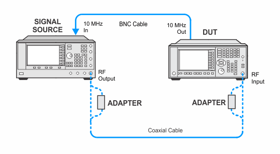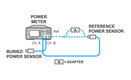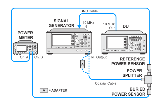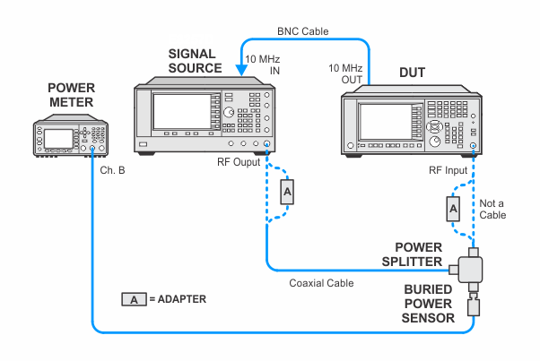
In the following setups, cables are designated as solid lines and direct connections are designated as dashed lines.
PXA — N9030B with frequency options 544 or 550 and without bandwidth options B2X or B5X
This adjustment is performed in two steps. The first step determines the frequencies which the frequency response will be adjusted (this step is called adaptive flatness). The second step determines the DUT frequency response correction at the frequencies determined in step 1.
The Adaptive flatness routine plots out the uncorrected frequency response on the DUT trace. This is done by placing the DUT trace in max hold then sweeping a source through the frequency band of interest. The trace can be seen as plot of conversion loss versus frequency. The trace data is then extracted from the DUT and processed.
At each correction frequency the DUT's conversion loss is measured. The loss is normalized to the loss at 50 MHz and this number is placed in the DUT memory. The DUT measurement application uses these stored corrections to make accurate amplitude measurements.
The related performance test for this adjustment is Frequency Response > 3.6 GHz.
Click here for troubleshooting.
|
Test Equipment |
Recommended Model Number |
|---|---|
|
Microwave Signal Generator #1 |
PSG Models |
|
Power Meter |
N1914B |
|
Millimeter Power Sensor
|
N8487A CFT |
|
Millimeter Power Splitter |
11667C |
|
Coaxial Cable, 2.4 mm |
8120-6164 |
|
BNC Cable |
8120-1840 |
|
Type-N (m) to 3.5 mm (m) adapter |
1250-1743 |
|
3.5 mm (f) to 3.5 mm (f) adapter |
83059B |
|
3.5 mm (f) to 2.4 mm (f) adapter |
11901B |
|
2.4 mm (f) to Type-N (m)
|
08487-60001 |
|
|
In the following setups, cables are designated as solid lines and direct connections are designated as dashed lines. |


