N9048B PXE
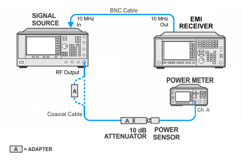
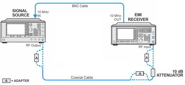
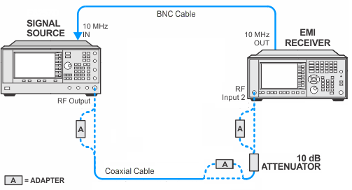
This adjustment generates an amplitude correction for RF Input 2 relative to RF Input 1. The basic adjustment inputs a 50 MHz, -25 dBm signal into RF Input 1. Amplitude corrections are turned off, and the amplitude is measured. The input signal is then moved to RF Input 2. The signal is measured and the RF1-RF2 amplitude difference is calculated. This difference is stored as a correction in the DUT memory.
|
Test Equipment |
Model Number1 |
|---|---|
|
Microwave Signal Generator |
PSG Models |
|
Power Meter |
N1914A |
|
Power Sensor |
E9304A Option H18 |
|
Fixed Attenuator, 10 dB |
8491A Option 010 |
|
Cable, coaxial 3.5 mm |
11500E |
|
Cable, BNC |
8120-1840 |
|
Adapter, Type-N (f) to 3.5 mm (f) |
1250-1745 |
|
Adapter, Type-N (m) to Type-N (m) |
1250-1475 |
|
Adapter, Type-N (m) to 3.5 mm (f)
|
1250-1744 |
|
Adapter, Type-N (m) to 2.4 mm (f)
|
11903D |
|
Adapter, 3.5 mm (f) to 3.5 mm (f)
|
83059B |
|
Adapter, 2.4 mm (f) to 3.5 mm (f)
|
11901B |
|