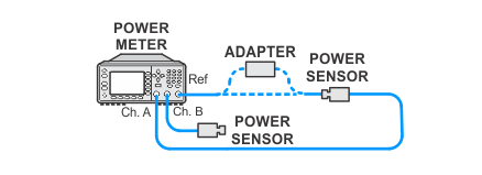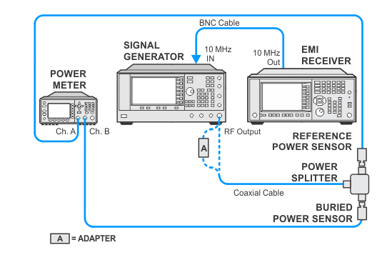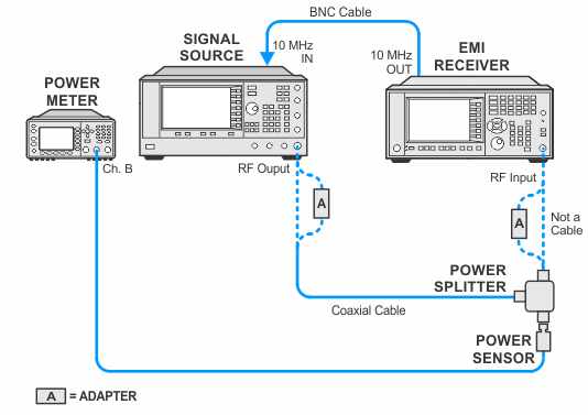
N9048B PXE with Option WF1
This procedure should only be performed on EMI receivers that are equipped with Option WF1 (Wideband Digital IF). The intent is to detect if the IF Frequency Response Adjustment needs to be run.
In this procedure, a test signal of –10 dBm is applied to the DUT. A reference amplitude is taken at the center frequency. The source frequency is then changed to a series of offset frequencies within the span of interest. At each offset frequency the source amplitude is maintained at –10 dBm, and the amplitude is measured by the DUT. The test is performed in Band 0.
Related adjustment: IF Frequency Response Adjustment
|
Test Equipment |
Model Number1 |
|---|---|
|
Microwave Signal Generator |
PSG Models |
|
Power Meter |
N1914A |
|
Microwave Power Sensor
|
N8485A CFT |
|
Microwave Power Splitter
|
11667B |
|
Millimeter Power Sensor
|
N8487A CFT |
|
Millimeter Power Splitter
|
11667C |
|
Cable, BNC |
8120-1840 |
|
Cable, coaxial 3.5 mm
|
11500E |
|
Cable, coaxial 2.4 mm
|
8120-6164 |
|
Adapter, Type-N (m) to 3.5 mm (m)
|
1250-1743 |
|
Adapter, 3.5 mm (f) to 3.5 mm (f)
|
83059B |
|
Adapter, 2.4 mm (f) to 3.5 mm (f)
|
11901B |
|
Adapter, 3.5 mm (f) to Type-N (m)
|
08485-60005 |
|
Adapter, 2.4 mm (f) to Type-N (m)
|
08487-60001 |
|


