
The Network Analyzer Freq Sweep Calibration is run from the Utilities Test Plan.
|
|
The Network Analyzer Freq Sweep Calibration is run from the Utilities Test Plan. |
N9048B PXE
The network analyzer used in certain adjustments must be calibrated prior to running the adjustment. The calibration will need to be repeated once every three days or if the connectors or cables have been disturbed. If it's been within the three day time-frame and the connectors and cables have not been disturbed, then the network analyzer calibration is not necessary and you may proceed with the adjustment.
|
|
Due to the sensitivity of this calibration, use good quality cables and adapters, minimize cable movement, and avoid bending the cables unnecessarily. It is recommended that you clean the cable ends and adapters before attaching to the network analyzer. |
|
Test Equipment |
Model Number1 |
|---|---|
|
Network Analyzer 1 |
N5247B Option 425
|
|
Power Meter |
N1914A |
|
Microwave Power Sensor
|
N8485A STD |
|
Millimeter Power Sensor
|
N8488A |
|
E-Cal Module, 3.5 mm
|
N4691D |
|
E-Cal Module, 2.4 mm
|
N4693D |
|
Cable, 2.4 mm (f) to 2.4 mm (m)
|
8121-2065 (or equivalent) |
|
Adapter, 2.4 mm (f) to 3.5 mm (f)
|
11901B |
|
Adapter, 2.4 mm (f) to 2.4 mm (f)
|
11900B (or equivalent) |
|
Adapter, 3.5 mm (m) to 2.4 mm (f)
|
11901D |
|
Adapter, 3.5 mm (f) to Type-N (m)
|
08485-60005 |
|
Adapter, 2.4 mm (f) to Type-N (m)
|
08487-60001 |
|
The power meter used in these procedures will be controlled by the network analyzer through the GPIB connection from the power meter to the network analyzer. Therefore the power meter needs to be added to the Keysight Connection expert via a remote GPIB interface.
The following steps will explain how to configure the PNA and the power meter's remote GPIB interface.
|
|
When using an NI IO card or NI USB-to-GPIB converter, be sure that the NI-VISA Passport for Tulip has been enabled to recognize and detect Keysight hardware. Refer to the following document for more detailed troubleshooting instructions: http://literature.cdn.keysight.com/litweb/pdf/5990-3731EN.pdf |
Ensure that Remote IO Server is enabled on the PNA.
Click on the gear in the upper-right, then select Settings > Remote IO Server options. Ensure Enable Remote IO Server and Auto-Start Remote IO Servers on Machine Startup are selected.
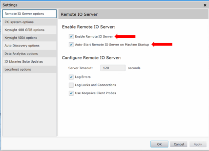
Close Keysight Connection Expert, and restart the Network Analyzer application by double clicking on the shortcut from the PNA front panel.
![]()
Make the GPIB cable connections so that the PNA can control the power meter.
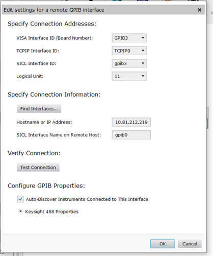
Configure the remote GPIB interface on the PC and in TME.
Click on Test Connection to verify that the connection was made.
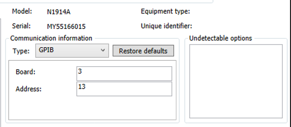
In Keysight Connection Expert, you should now see the remote GPIB interface you have created, and the power meter that is connected (by GPIB) to the controller of the PNA.
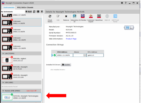
Now in TME Station Administration, map the power meter to the appropriate board and address. Using the example above, the correct board is 3 and the address is 13.
Follow the steps below to calibrate the network analyzer. Click on the links to show the calibration procedures and connection images.
|
|
In the following calibration procedures, the 2.4 mm to 3.5 mm barrel adapter (for Options < 544) or 2.4 mm to 2.4 mm barrel adapter (for Option 544) attached to the cable on Port 1 of the network analyzer must remain attached and properly torqued throughout the entire calibration procedure. Disturbing the adapter or the cable connection to the network analyzer will void the calibration. |
|
|
In all procedures using a power meter, the network analyzer must be connected to the LAN. |
Connect the 2.4 mm (f) end of the cable to Port 1 of the network analyzer.
Connect the 2.4 mm (m) end of the cable to a 2.4 mm (f) to 3.5 mm (f) barrel adapter (for options < 544) or 2.4 mm (f-to-f) barrel adapter (for Option 544).
Connect the barrel adapter to the power sensor.
When disconnecting from the power sensor after the calibration is complete, be sure that the barrel adapter stays on the cable and is properly torqued.

Leave the 2.4 mm cable attached to Port 1 of the network analyzer. Leave the barrel adapter on the cable and attach it to Port B of the ECal module.
Attach Port A of the ECal module to Port 2 of the network analyzer using a 2.4 mm (f) to 2.4 mm (m) cable. Use an appropriate adapter (11901D) for options < 544.
When disconnecting the cable/adapter from Port B of the ECal module, be sure that the barrel adapter stays on the cable and is properly torqued.
Leave the 2.4 mm cable attached to Port 1 of the network analyzer. Leave the barrel adapter on the cable and attach it to the power sensor.
When disconnecting from the power sensor after the verification is complete, be sure the barrel adapter stays on the cable and is properly torqued.

