![]()
Prior to this calibration, ALC Dynamic must have been successfully completed.
This adjustment is specific to ALC PC boards part number E8251-60375 or greater. Previous ALC boards do not have the ability to clamp the output power, and thus do not require this adjustment.
|
|
Prior to this calibration, ALC Dynamic must have been successfully completed. |
This adjustment will clamp the output power of the DUT to a specified value to insure there will not be a spike in power beyond a specified level during changes in settings. The adjustment operates by first setting the DUT frequency and the power to appropriate levels to clamp the DUT. The DAC is incremented until the internal ABUS ALC integrator voltage is leveled, then decremented until it is unleveled, and lastly is incremented by one count which was the last leveled DAC value. This DAC value is then stored to the array.
|
Test Equipment |
Preferred Model |
Alternate Model(s) |
|
50 ohm terminator |
Depending on the DUT RF Output Connector, choose: 85138B (2.4mm) |
20 dB attenuator |
|
|
|
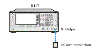
Connect all test equipment as shown.
Connect GPIB cables to all GPIB-controlled test equipment.
While performing this adjustment, follow all instructions on the controller display.
Setup for Power Clamp

If this adjustment fails, perform the following steps in order:
Verify that the GPIB cable is connected between the controller and the signal generator being calibrated and rerun the adjustment.
If this adjustment still fails after step 1, refer to the troubleshooting section of the signal generator's service guide. If you do not have a printed copy of the service guide (Option OBW), one is available either on the CD-ROM that came with your signal generator shipment or on the Keysight Website.
If ou cannot correct the problem using the troubleshooting procedures in the Service Guide, obtain service from Keysight Technologies. Refer to Contacting Keysight Technologies.