![]()
-
All test equipment requires a 30 minute warmup period to ensure accurate performance.
-
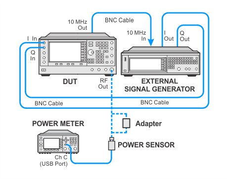
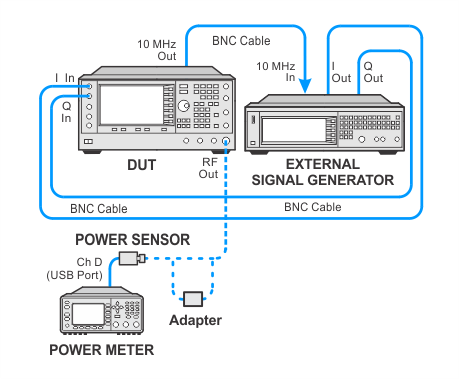
In the following test setup, cables are designated as solid lines and direct connections are designated as dashed lines.
This test compares the digital modulation power level to the CW power level at the same frequency. The DUT’s external I/Q inputs are driven by an external baseband signal generator. A power meter and power sensor are used to measure the DUT output power in CW mode and in digital-modulation mode. The difference between the two power levels is compared to the specifications.
The test is performed with two different modulation formats: QPSK and GSM (GMSK).
|
Test Equipment |
Recommended Models |
Alternate Model(s) |
|
Power Meter |
N1914A1 |
E4419A/B (with firmware A2.09.01 or greater when using N-Series sensors) |
|
Power Sensor (Mid Frequency) |
N8487A |
8487A Opt H842 The E9300A H25 E-Series power sensor does not have sufficient bandwidth to measure the digitally modulated signal. |
|
External Baseband Signal Generator |
N5182B Opt 656 or 657 |
N5182A Opt 651, 652, or 654 E4438C Opt 402 and (001, 002, 601, or 602), |
|
|
|
Connect all test equipment as shown.
Connect GPIB cables to all GPIB-controlled test equipment.
While performing this test, follow all instructions on the controller display.
This test uses flexible power sensor channel assignment and will identify the channel that a power sensor is connected to using the ability of "smart" sensors such as the N848xA, U848xA, and E930xA series to report their full model and serial number. Legacy 848x series power sensors are unable to provide their model or serial number, but their channel is identified during the sensor calibration process by identifying the channel of the sensor connected to the calibrator.
If the wrong legacy power sensor is connected to the calibrator during this process, the error can be resolved by disconnecting and reconnecting the power sensor to the power meter which will force a new calibration.
Select from the links below for connection setups depending on the power sensor selection. To expand all, click the Expand All button  in the toolbar (webhelp only).
Power sensor calibration — standard sensors
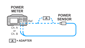
Setup for DUT using an external baseband generator — standard sensor channel A
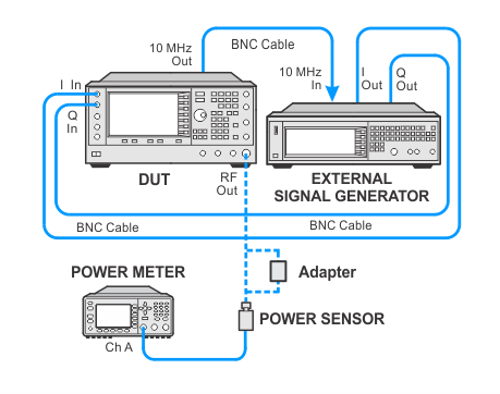
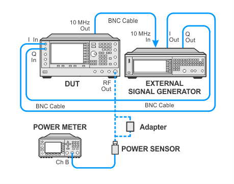
Setup for DUT using an external baseband generator — standard sensor channel B
Power sensor calibration — USB sensors
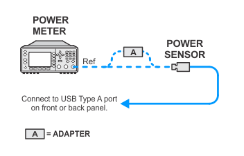
Setup for DUT using an external baseband generator — USB sensor channel C
Setup for DUT using an external baseband generator — USB sensor channel D
If this performance test fails, perform the following steps in order:
Check the equipment setup (see above). If the setup is incorrect, make the necessary corrections and rerun the Performance Test.
If an "IQ Calibration Failed" error dialog occurs at the beginning of the test, manually run the IQ calibration using the front panel and observe the errors on the DUT. If successful, repeat the test.
If this test fails with the equipment set up properly, refer to the troubleshooting section of the signal generator's service guide. If you do not have a printed copy of the service guide (Option OBW), one is available either on the CD-ROM that came with your signal generator shipment or on the Keysight Website.
If you cannot correct the problem using the troubleshooting procedures in the Service Guide, obtain service from Keysight Technologies. Refer to Contacting Keysight Technologies.
