Power level accuracy is the difference between the power level indicated by the unit under test (DUT) and the true power delivered by the DUT.
Direct absolute power measurements are made with a power meter for higher power levels. A spectrum analyzer is used for all lower power measurements. For the E8257N and E8257D Option H42, this test also measures the relative power flatness at specified power levels.
Test Equipment |
Recommended Models |
Alternate Model(s) |
Power Meter |
N1914A13 |
E4419A/B (with firmware A2.09.01 or greater when using N-Series sensors) |
Power Sensor (Low Frequency) |
E9304A H19 |
E9304A1, 2 |
Power Sensor (Mid Frequency) |
N8487A3 |
8487A H843, 4 |
Power Sensor (High Frequency) |
V8486A H677 |
N8488A |
Coaxial to V Band Adapter |
V281A10 |
|
Spectrum Analyzer |
N9030B Opt 5xx11, Pxx12, MPB16 |
E444xA9 Opt 110 and 12316 N9030A Opt 5xx11, MPB16, Pxx12 |
Not allowed for the following product configurations:
E8257D with Option 1EU and H26;
E8257D with Option 1EU and 532;
E8257D with Option 1EU and 540;
E8257N with Option 1EU;
E8267D without Option H18, and with serial number 50420000 or greater or if retrofitted with Option
1EU;
E8663D with Option 1EU.
The dynamic
power range of this sensor is insufficient for these models.
Not allowed for the following product configurations:
E8663D with Option 509;
The dynamic frequency range of this sensor is insufficient for this model.
Not allowed for the following product configurations:
E8257D with Option 521;
E8257D with Option 520 and 1EA;
E8257D with Option 520 and 1EU;
Although the dynamic power range of this sensor is insufficient for the configurations listed above, it is adequate for configurations not listed, such as E8257D with Option 532, etc.
Option H84 provides reflection coefficient data.
Required for the following product configurations:
E8257D with Option 521;
E8257D with Option 520 and 1EA;
E8257D with Option 520 and 1EU;
The dynamic power range of this sensor is required for these models.
Also allowed for the following product
configurations:
E8257D with Option 520;
E8267D with Option 520.
Only allowed for the following product configurations:
E8257D with Option 520 and without 1EA and 1EU;
E8257D with Option H26;
E8267D with Option 520.
Option H67 is an ANSI Z540-1 calibration for the V8486A Power Sensor with a V281A Connector Adapter (connected together).
Not allowed for the following product configurations:
E8257D with Option 532, 540, 550, or 567;
E8257N;
E8267D with Option 532 or 544.
Select any model of PSA spectrum analyzer (E4440A, E4443A,E4445A, E4446A, E4447A, E4448A) that has a maximum frequency greater than or equal to the maximum frequency of the unit under test. An E4448A is required for units with Option 567. The E4448A frequency range is adequate for all PSG-D frequency configurations.
Not required if the N8488A or U8488A is used.
Select any option of PXA spectrum analyzer (503, 508, 513, 526, 543, 544, 550) that has a maximum frequency greater than or equal to the maximum frequency of the unit under test. An N9030A/B Option 550 is required for units with Option 567. The N9030A/B Option 550 frequency range is adequate for all PSG-D frequency configurations.
Select any preamplifier option for the PXA spectrum analyzer (P03, P08, P13, P26, P43, P50) that has a maximum frequency greater than or equal to the maximum frequency of the unit under test. An N9030A/B Option P50 is used for units with Option 567. The N9030A/B Option P50 frequency range is adequate for all PSG-D frequency configurations.
Power meter N1914A with serial numbers ranging between MY00000000—MY53040007 require Service Note 07 to be applied for measurement repeatability. Please have this service note applied or verify it was applied before using this power meter. The affected service note is: N1914A-07 Service Note.
Requires power meter N1914A with USB ports. Refer to the main Required Test Equipment table.
Only allowed for the following product configurations:
E8257D with Option 520 and without 1EA and 1EU;
E8257D with Option H26 or 532;
E8267D with Option 520 or 532.
Microwave Preselector Bypass Option MPB (PXA) or 123 (PSA) is used by not required by this test.
|
|
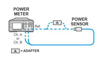
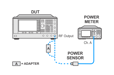
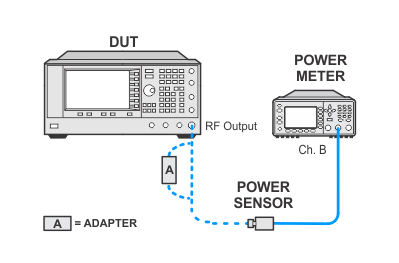
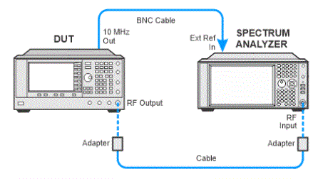
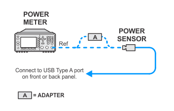
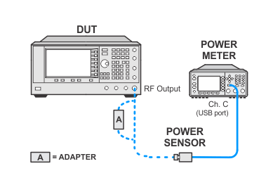
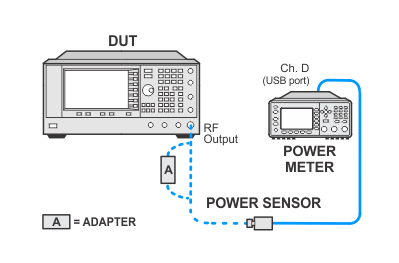
Connect all test equipment as shown.
Connect GPIB cables to all GPIB-controlled test equipment.
While performing this test, follow all instructions on the controller display.
This test uses flexible power sensor channel assignment and will identify the channel that a power sensor is connected to using the ability of "smart" sensors such as the N848xA, U848xA, and E930xA series to report their full model and serial number. Legacy 848x series power sensors are unable to provide their model or serial number, but their channel is identified during the sensor calibration process by identifying the channel of the sensor connected to the calibrator.
If the wrong legacy power sensor is connected to the calibrator during this process, the error can be resolved by disconnecting and reconnecting the power sensor to the power meter which will force a new calibration.
Select from the links below for connection setups depending on the power sensor selection. To expand all, click the Expand All button in the toolbar (webhelp only).
Power sensor calibration — standard sensor
Power sensor calibration — USB power sensors
If this performance test fails, perform the following steps in the following order:
Check the equipment setup (see above). If the setup is incorrect, make the necessary corrections and rerun the Performance Test.
Sometimes noise from nearby test equipment can affect low-level measurements. Errors may be caused even if the power meter is stacked on top of the spectrum analyzer.
Inspect all RF cables. If semi-rigid cables are used, check for cracks in the shielding or at the connectors. RF leakage to/from the cables generally cause problems at higher frequencies (>2 GHz) and low power levels (<-100 dBm).
Verify that the spectrum analyzer does not have a residual spur at the frequency being measured. Sometimes a spur will limit how low in power the spectrum analyzer can measure.
Make sure that all test equipment is using the same power outlet. Ground loops can cause problems at low power levels. This type of problem will most likely show up at lower frequencies.
Make sure all covers on the DUT are secure and that all screws are in place.
Verify the amplifier being used meets its gain specifications.
Make sure all connections in the measurement system are torqued properly. Loose or damaged connections result in RF leakage and errors result at low power levels.
Make sure all test equipment (including the amplifier) has been turned on at least 30 minutes.
If this test still fails after above steps, refer to the troubleshooting section of the signal generator's service guide. If you do not have a printed copy of the service guide (Option OBW), one is available either on the CD-ROM that came with your signal generator shipment or on the Keysight Website.
If you cannot correct the problem using the troubleshooting procedures in the Service Guide, obtain service from Keysight Technologies. Refer to Contacting Keysight Technologies.