
- All test equipment requires a 30 minute warmup period to ensure accurate performance.
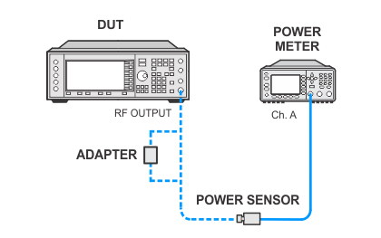
- In the following adjustment setup, cables are designated as solid lines and direct connections are designated as dashed lines.
Use this calibration to optimally set the ALC MOD DRIVER BIAS/GAIN DAC and the ALC MOD OFFSET DAC on the output boards. The ALC MOD DRIVER BIAS/GAIN DAC primarily is used to accommodate unmatched VBE values in the drivers, but it has a strong influence on the modulator gain.
The goal of this calibration is to adjust the ALC MOD DRIVER BIAS/GAIN DAC until the ALC modulator gain is balanced about its nominal design center. Then the ALC MOD OFFSET DAC is adjusted until the gain of the modulator forces the loop integrator ABUS node to zero.
Equipment: Required only if an output board is E4400-60659 or later.
|
Test Equipment |
Recommended Model |
Alternate Model |
|
Power Meter |
N1914B |
N1914A1 E4418A |
|
Power Sensor |
N8482A |
E9304A |
|
|
|
|
|
|
If the signal generator displays a message indicating that the current power level accuracy calibration data is invalid, run the Power Flatness adjustment to correct the calibration data. |
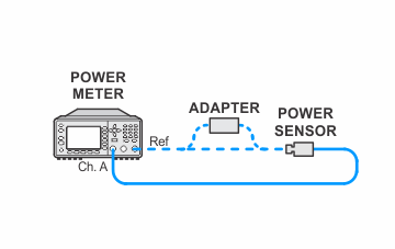
Power Meter Zero and Cal Setup
If this adjustment fails, perform the following steps in order:
Check the equipment setup (see above). If the setup is incorrect, make the necessary corrections and rerun the adjustment.
If this adjustment fails with the equipment set up properly, refer to the troubleshooting section of the signal generator's service guide. If you do not have a printed copy of the service guide (Option OBW), one is available either on the CD-ROM that came with your signal generator shipment or on the Keysight Website.
If you cannot correct the problem using the troubleshooting procedures in the Service Guide, obtain service from Keysight Technologies. Refer to Contacting Keysight Technologies.
