
- All test equipment requires a 30 minute warmup period to ensure accurate performance.
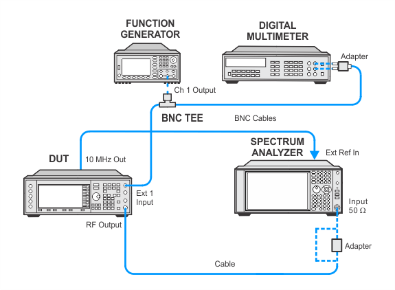
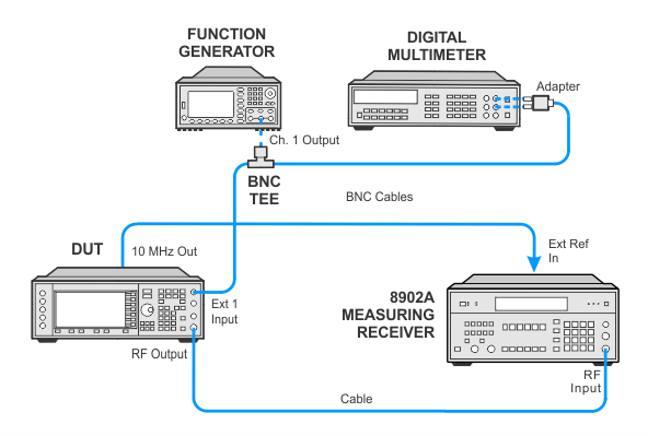
- In the following adjustment setup, cables are designated as solid lines and direct connections are designated as dashed lines.
This adjustment is used to set the FM and PM deviation at rates above the loop bandwidth (out-of-band) so they will equal the deviation rates within the loop bandwidths (in-band). The loop bandwidth of the synthesizer phase-locked loop is approximately 5 kHz.
During this adjustment, a function generator and a digital multimeter are connected to a BNC tee on the EXT1 input. The function generator is set to a desired rate and the amplitude is set to a desired level using the digital multimeter. Once the amplitude is set, deviation measurements are made with the spectrum analyzer (preferred solution) or a measuring receiver (alternate solution).
At each FM and PM rate, the out-of-band performance is matched to the in-band performance. This is accomplished by changing the rate with the function generator and making deviation measurements with the spectrum analyzer (preferred solution) or a measuring receiver (alternate solution). The appropriate correction is determined through an iterative process and stored in the instrument, resulting in a flat FM and PM response vs. rate.
This test supports two equipment setups using either a spectrum analyzer or a measuring receiver. The spectrum analyzer is the preferred solution.
The preferred solution uses a spectrum analyzer with Analog Demodulation Measurement Application to demodulate the signal and measure the deviation.
|
Test Equipment |
Recommended Models |
Alternate Models |
|
Spectrum Analyzer |
N9030B Opt 5xx1, N9063EM0E Analog Demodulation Measurement Application |
N9030A Opt 5xx1 and N9063EM0E Analog Demodulation Measurement Application2 E444xA3 Opt 233 |
|
Function Generator |
33622A |
33250A |
|
Digital Voltmeter |
3458A Opt 002 |
34470A |
|
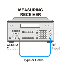
The alternate solution uses an 8902A measuring receiver.
|
Test Equipment |
Recommended Models |
Alternate Models |
|
Measuring Receiver |
8902A |
|
|
Function Generator |
33622A |
33250A |
|
Digital Voltmeter |
3458A Opt 002 |
34470A |
|
|
|
Calibration Setup for 8902A:
Test Setup with Measuring Receiver
If this adjustment fails, perform the following steps in order:
Check the equipment setup (see above). If the setup is incorrect, make the necessary corrections and rerun the adjustment.
If this adjustment fails with the equipment set up properly, refer to the troubleshooting section of the signal generator's service guide. If you do not have a printed copy of the service guide (Option OBW), one is available either on the CD-ROM that came with your signal generator shipment or on the Keysight Website.
If you cannot correct the problem using the troubleshooting procedures in the Service Guide, obtain service from Keysight Technologies. Refer to Contacting Keysight Technologies.
