AM distortion is defined as the square root of the ratio of the power contained in the harmonics of the demodulated AM waveform to the power of the fundamental component of the demodulated waveform.

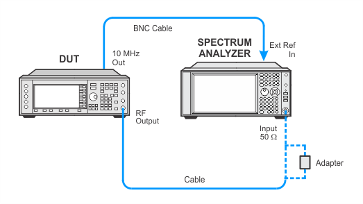
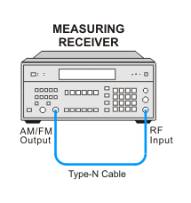
This test supports two equipment setups using either a spectrum analyzer or a measuring receiver. The spectrum analyzer is the preferred solution.
The preferred solution uses a spectrum analyzer with Analog Demodulation Measurement Application to demodulate the signal and measure the deviation.
|
Test Equipment |
Critical Specifications for This Test |
Recommended Models |
Alternate Models |
|
Spectrum Analyzer |
AM Demodulated Distortion (< 50% AM) ≤ 0.3% |
N9030B Opt 5xx1, N9063EM0E Analog Demodulation Measurement Application |
N9030A Opt 5xx1 and N9063EM0E Analog Demodulation Measurement Application2 E444xA3 Opt 233 |
|
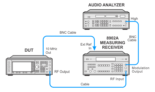
The alternate solution uses an 8902A measuring receiver to demodulate the signal and measure the deviation.
|
Test Equipment |
Critical Specs for This Test |
Recommended Models |
Alternate Models |
|
Measuring Receiver |
AM Demodulated Distortion (< 50% AM) ≤ 0.3% |
8902A |
|
|
Audio Analyzer1 |
Distortion (20 Hz to 20 kHz) < –80 dB* * The distortion accuracy of the 8903B is worse than the specified AM distortion of the UUT. Therefore, the indicated distortion must be greater than the specification by at least the amount of the 8903B distortion measurement accuracy. |
8903B |
|
|
Mixer1 |
RF/LO Freq Range: 800 to 3000 MHz IF Frequency Range: 10 to 1000 MHz RF 1 dB compression: +1 dBm |
0955-2225 |
M/A-COM MDC-164 |
|
Local Oscillator1 |
Frequency Range: 800 to 2500 MHz Amplitude : +16 dBm |
E8267D Opt UNR or UNX or UNY |
E4428C Opt 503 or 506 E8241A Opt UNJ E8247C Opt UNR E8257D Opt UNR or UNX or UNY E8663B N5181B/82B Opt 503 or 506 |
Not used for ESGs with a frequency range of < 2 GHz.
|
|
|

Calibration Setup

AM Distortion CW Frequency < 1300 MHz Test Setup

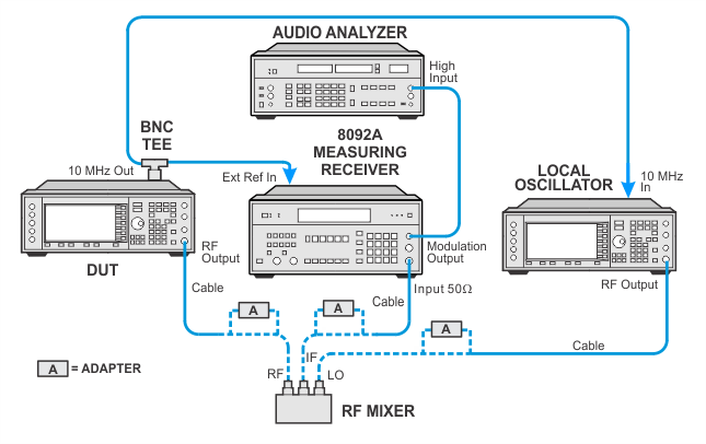
AM Distortion CW Frequency > 1300 MHz Test Setup

If this performance test fails, perform the following steps in order:
Check the equipment setup (see above). If the setup is incorrect, make the necessary corrections and rerun the performance test.
If this test fails with the equipment set up properly, refer to the troubleshooting section of the signal generator's service guide. If you do not have a printed copy of the service guide (Option OBW), one is available either on the CD-ROM that came with your signal generator shipment or on the Keysight Website.
If you cannot correct the problem using the troubleshooting procedures in the Service Guide, obtain service from Keysight Technologies. Refer to Contacting Keysight Technologies.
