Amplitude modulation distortion measures the distortion of the AM signal when using the internal modulation source. The distortion is defined as the square root of the ratio of the power contained in the harmonics of the demodulated AM waveform to the power of the fundamental component of the demodulated waveform:

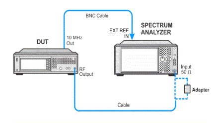
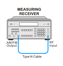
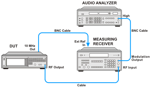
This test supports two equipment setups using either a spectrum analyzer or a measuring receiver. The spectrum analyzer is the preferred solution.
The preferred setup uses a spectrum analyzer with Analog Demodulation Measurement Application to both demodulate the signal and measure the distortion.
|
Test Equipment |
Critical Specifications for This Test |
Recommended Model |
Alternate Model |
|
Spectrum Analyzer |
AM Distortion |
N9030B Opt 5xx1, N9063EM0E Analog Demodulation Measurement Application |
N9030A Opt 5xx1, N9063EM0D Analog Demodulation Measurement Application2 E444xA3 Option 233 |
|
Alternatively, an 8902A measuring receiver is used to demodulate the AM signal, and an 8903B audio analyzer will measure the demodulated distortion.
|
Test Equipment |
Critical Specifications for This Test |
Recommended Models |
|
Measuring Receiver |
AM Distortion |
8902A |
|
Audio Analyzer |
AM Distortion |
8903B |
|
|
|


If this performance test fails, perform the following steps in order:
Check the equipment setup (see above). If the setup is incorrect, make the necessary corrections and rerun the performance test.
Refer to the troubleshooting section of the service guide. If you do not have a printed copy of the service guide (Option OBW), one is available either on the CD-ROM that came with your signal generator shipment or search for your signal generator model number on the Keysight website.
If necessary, obtain service from Keysight Technologies. Refer to Contacting Keysight Technologies.
