Maximum Output Power
(N5161A / N5162A / N5166B / N5171B / N5172B / N5181A / N5181B / N5182A / N5182B / N5182BX07 / N5182N)
This test verifies that the maximum output power from the UUT meets specifications. During this test, the signal generator is set to its maximum settable output power and a measurement is performed using a power meter.
|

|
The N5182BX07 requires the Extender Power Alignment procedure to be performed prior to running Performance Verification test plans. Refer to the N5182BX07 User's Guide for instructions on running the Extender Power Alignment. To access the User's Guide, go to Keysight support.
|
Required Test Equipment
|
Test Equipment
|
Critical Specifications for This Test
|
Recommended Model
|
Alternate Model(s)
|
|
Power Meter
|
None
|
N1914A1
|
E4419A/B
E4418A/B
N1911A/12A/13A
|
|
Power Sensor
|
None
|
E9304A, E9304A H18
use with standard model DUTs
E9304A Opt H19
use with Opt 1EA DUTs or standard
model DUTs
|
N8482A
N8482A CFT
use with standard model DUTs
U8481A2 Opt 200
U8485A2 Opt 200
|
|
Power Sensor
|
None
|
E9304A Opt H19
|
None
|
|
Signal Generator
|
None
|
N5182B Options 506, 1EA, and FRQ
|
|
|
Connections and Setup Procedures
|
|
- All test equipment requires
a 30 minute warmup period to ensure accurate performance.
- In the following test setup,
cables are designated as solid lines and direct connections are designated
as dashed lines.
|
- Connect
all test equipment as shown.
- Connect
GPIB cables to all GPIB-controlled test equipment.
- While
performing this test, follow all instructions on the
controller display.
Flexible power sensor channel assignment
This test uses flexible power sensor channel assignment and will identify the channel that a power sensor is connected to using the ability of "smart" sensors such as the N848xA, U848xA, and E930xA series to report their full model and serial number.
Select from the links below for connection setups depending on the power sensor.
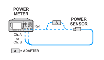
Power sensor calibration — standard sensor
|
|
The power sensor calibration is performed once every 24 hours or if the power sensor has been disconnected.
|
Measurement setup — standard sensor channel A
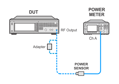
Measurement setup — standard sensor channel A
N5182BX07
ToPSChA.gif)
Measurement setup — standard sensor channel B
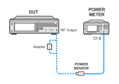
Measurement setup — standard sensor channel B
N5182BX07
ToPSChB.gif)
Power sensor calibration — USB sensor
|
|
The power sensor calibration is performed once every 24 hours or if the power sensor has been disconnected.
|
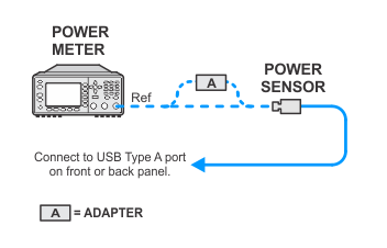
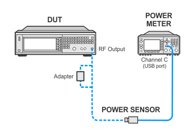
Measurement setup — USB sensor channel C
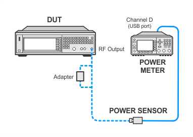
Measurement setup — USB sensor channel D
In Case of Difficulty
If this performance test fails, perform the following steps in order:
-
Check the equipment setup (see above). If the setup
is incorrect, make the necessary corrections and rerun the performance
test.
-
Refer to the troubleshooting section of the service
guide. If you do not have a printed copy of the service guide (Option
OBW), one is available either on the CD-ROM that came
with your signal generator shipment or search for your signal generator
model number on the Keysight website.
-
If necessary, obtain service from Keysight Technologies.
Refer to Contacting
Keysight Technologies.

 Setup using standard power sensors