
Installation packages available for download at: http://www.cal.software.keysight.com
Included in this topic is:
Please see the Readme.txt for minimum system requirements to run this application.
|
|
Installation packages available for download at: http://www.cal.software.keysight.com |
Close all applications
Install Keysight N7800A Test Management Environment (TME). See the TME Readme.txt for TME installation instructions.
Install the Keysight N783A Power Meters Calibration Application by double-clicking on the setup.exe previously downloaded.
Follow the instructions on the screen to install.
There are two ways to install TME and its applications:
Network Installations - Equipment and test data information is stored in a central location (the TME Server). This data is shared among a set of TME Clients. Multiple test stations can then have access to this central information.
Local Installations - Everything is installed on one PC
In a network installation, order information is stored centrally and can be accessed by any TME client in the network. This allows you to combine data from tests that were run on multiple stations into a single report. Equipment data and order information are also accessible from any station
To set up a new TME network, please see the instructions in the TME help system.
If TME is setup as a network installation, the application will automatically be setup as a network on that machine when the installation is executed. The application server must be installed before any clients can be installed.
|
|
The installation of the application network data must take place on the same PC that installed the TME network data. |
TME client must also be installed on all machines intending to run this application as clients of the network.
To install an application on a network follow the following steps:
Find the PC where the TME network was installed (Shows “TME Server” in Programs and Features).
Run Setup.exe for the application on that PC. This will install all networked components for that application.
Install application clients:
TME clients will be asked to install the application the next time TME is started.
Or
Applications can be installed by running the setup file from the network directory:
\\FileServer\Test Management Environment\Install\(AppName)\(AppName)ClientSetup.exe
|
|
The client setup must be run from this location. It should not be moved or renamed. |
TME must be installed on the target PC before the application installation can occur.
On a local installation, all application data is stored on the target PC. Once TME has been installed as a local installation the application installation will automatically install locally when executed. Order information, test results, and equipment data will not be shared with other users.
To uninstall TME or any TME application select that package from Programs and Features on the Control Panel.
To uninstall an application client, select that package from Programs and Features on the Control Panel and click Remove.
|
|
Data will not be lost if only a client is uninstalled. Other clients will still have access to the data in the network. |
To uninstall an application server:
Follow the directions above to uninstall all application clients.
Once all application clients have been uninstalled, uninstall the application server from the PC where the server installation was performed.
Select the application server from Programs and Features on the Control Panel and click Remove.
To uninstall an application local installation, select that package from Programs and Features on the Control Panel and click Remove.

There are two choices for test variants you can select when setting up your test system for P-Series power meters:
Normal
You cannot mix test results from different test variants on a single test report. In order to show a complete test report, all tests in one of the test variants must be run.
The Factory Recommended variant is the suite of tests that the factory recommends. This variant offers an updated test method for instrument linearity measurements for Peak and Average paths. The Linearity test is replaced by two tests: Absolute Accuracy and Instrumentation Linearity.
This variant replaces existing internal Peak and Average Path linearity measurements with separate external measurements:
|
Average Path |
This path is tested by the existing Absolute Accuracy test using a range calibrator, function generator, and digital multimeter. |
|
Peak Path |
This path is tested by the new Instrumentation Linearity test using an audio analyzer and the new N1915A Peak Power Meter Test Adapter. |
The Normal Variant is the suite of tests from the previous release version. This variant allows the operator to fully test the DUT without having to obtain new test equipment (audio analyzer and the N1915A Peak Power Meter Test Adapter).
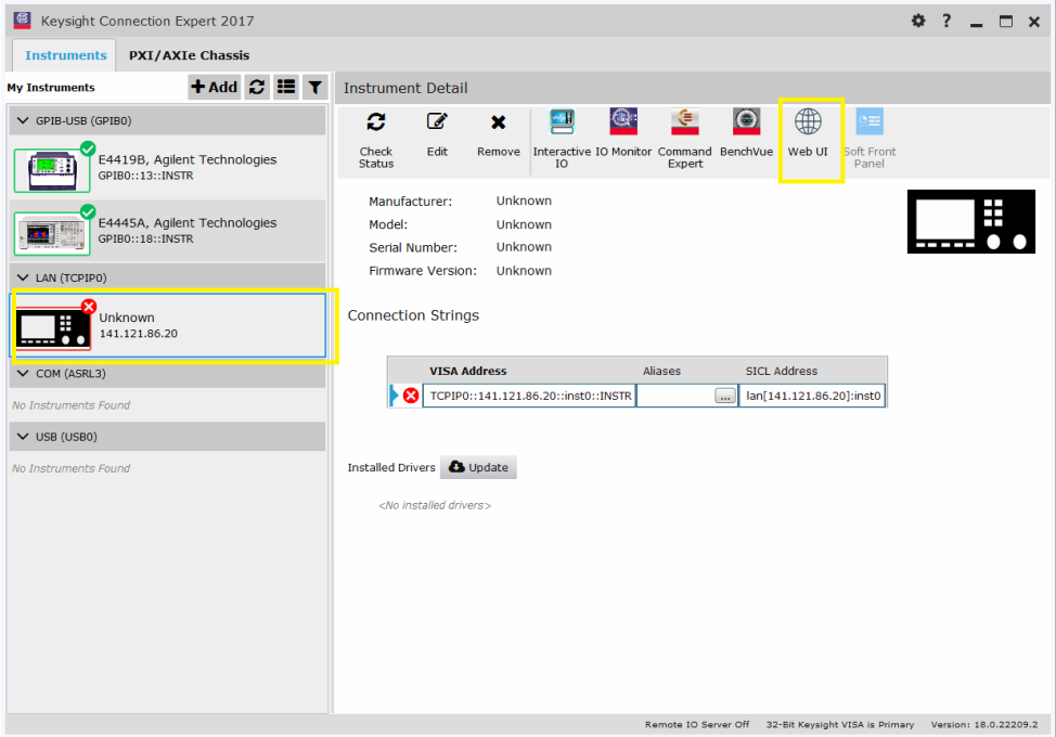
When creating a new order for the N8262A power meter, TME will require the IP address or hostname to be entered. For the N8262A power meter, this information is not obtained via autodetect and must be entered manually. The steps below explain how to obtain the IP address or hostname. The default format of the hostname is K-N8262A-12345 (or A-N8262A-12345 depending on Agilent or Keysight firmware version) where 12345 is the last 5 digits of the serial number of the power meter.
From Keysight Connection Expert in the Instruments, My Instruments window, select the Unknown instrument under the LAN choices on the left. This will display the Instrument Detail pane on the right. To confirm that the IP address displayed is for the N8262A power meter, click on the Web UI icon at the top of the Instrument Detail pane.
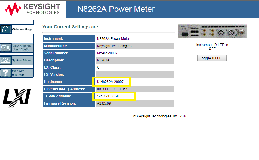
Clicking on the Web UI icon will display the window below that shows instrument details including the IP address and hostname. This information can be entered in the TME UUT Setup dialog box shown in the next step.
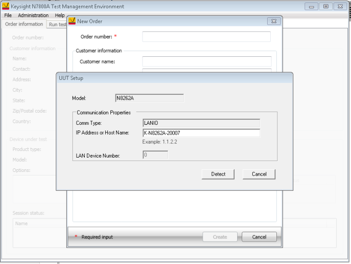
Enter the IP address or hostname in the in the UUT Setup dialog box.
This section describes the preparation of the instruments used by the test software at a given test station. The test software does not check instruments for proper operation on the GPIB bus before attempting to perform tests.
The typical GPIB address configuration for a test station is:
|
Spectrum Analyzer |
18 |
|
Network Analyzer |
16 |
|
Power Meter |
13 |
|
Frequency Counter |
3 |
|
Source |
19 |
It is recommended that the operator follow the steps below to manually check for proper connection of the GPIB devices before performing tests on a newly connected test station.
Note the GPIB address of each instrument associated with the test station/test plan defined earlier.
Connect a power cord to each instrument, and then connect each instrument to the computer serving as the GPIB controller.
Power up all the instruments on the GPIB bus.
Check each GPIB instrument for proper communication over the bus and the required detectable options. Follow the process described in "Checking GPIB Bus Devices" below.
|
|
When checking for basic operation of each GPIB device or when checking for detectable options on a given device, you may have to look up the actual command for retrieving the identification string before performing these procedures. |
The following applies only to Keysight/Agilent/HP GPIB cards; a different program is used for National Instruments GPIB cards.
Start the VISA Assistant:
Select
the "hp" or the IO box on the right side of the task bar or
access it through: Start/Programs/Keysight
I_O Libraries/VISA Assistant.
Check for all expected GPIB devices:
Verify
that all expected GPIB devices are shown in the left window.
If a device is missing, correct the problem and restart the VISA
Assistant.
Check all GPIB device addresses:
Verify that no two GPIB addresses are the same.
Follow the process described in the user manual for the device if an address needs to be changed. The following numbers are reserved and are not available for GPIB addresses: 0, 1, 21, 31.
After changing the address of the device, go to the Administration area, highlight the device icon, and enter the correct GPIB address into the Address field.
Check for basic operation of each GPIB device:
|
|
If an instrument does not support SCPI, refer to the user guide for your product to learn more about checking the basic operation of its GPIB. |
Select a GPIB device to highlight it.
Select the "Formatted I/O" tab (expand the window if needed).
Select the SCPI radio button.
Select on the "*IDN?" button.
Check to see that the expected model number is contained in the response text string.
Check for detectable options on a given device:
Select a GPIB device to highlight it.
Select the "Formatted I/O" tab.
Select the SCPI radio button.
Enter "*OPT?" and select "viQueryf".
A "detectable" option is one that can be detected through the GPIB.
Connect the power meter to the computer serving as the GPIB controller.
Power up the power meter.
Connect the LAN cable from the LAN connector on the power meter to an empty connector on your internal local area network or LAN hub. Please put the power meter on the same switch or hub as your PC.
Turn on power and wait until the PWR LED and LAN LED on the front panel of the power meter turn solid green.
|
|
Please refer to Keysight N8262A P-Series Modular Power Meter Installation Guide (N8262-90005) for detail information on configuring the LAN interface as well as connecting to the P-Series modular power meter. |
Allow sufficient warm-up time for the test equipment and the UUT. All UUT requires a 30-minute warm-up period to ensure accurate performance. For the test equipment, refer to the product operating and service manual for the warm-up period.
Protection against electrostatic discharge (ESD) is essential while connecting, inspecting, or cleaning connectors attached to a static-sensitive circuit (such as those found in test sets). Static electricity can build up in your body and can easily damage sensitive internal circuit elements when discharged. Static discharges too small to be felt can cause permanent damage. Devices such as calibration components and units under test (UUTs) can also carry an electrostatic charge. To prevent damage to the test set, components and devices:
Always wear a grounded wrist strap having a 1 million Ohm resistor in series with it when handling components and devices or when making connections to the test set.
Always use a grounded antistatic mat in front of your test equipment.