Noise Receiver Linearity Performance Test
Alternate Solution, Normal Variant
|

|
-
There are two solutions for the Noise Receiver Linearity test using the Normal Variant test plan: Preferred and Alternate. Refer to the Overview page to determine which solution applies to your PNA-X model number.
-
Because of the sensitivity of the this test, it is recommended to leave the power sensor undisturbed and connected to the test set for at least 30 minutes prior to running the test.
-
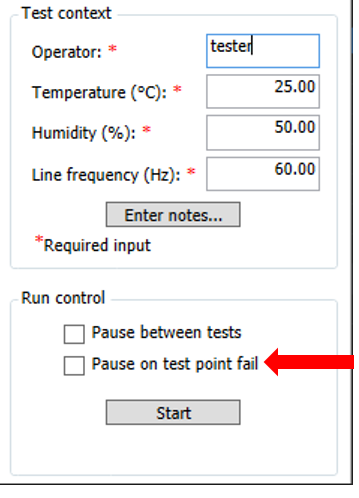
Be sure that  Pause on test point fail is not selected for this test. Pause on test point fail is not selected for this test.
|
Noise Receiver Linearity is a measure of the receiver’s relative measurement
accuracy as a function of received power.
The Noise Receiver Linearity measurement will be made by injecting a
controlled CW power into the port and using the noise receiver to measure
the power (the receiver measurement minus the cold noise correction).
The input power is then set to a new power level and another receiver
measurement is made (the receiver measurement minus the cold noise correction).
The difference between the injected power change and the measured power
change is the noise receiver linearity error.
For troubleshooting help, see Noise Receiver Linearity Troubleshooting.
Required Test Equipment
|
Test Equipment1
|
Recommended Model
|
Alternate Model
|
|
Signal Generator
(SignalGenerator1)
|
E8257D
|
N5183B
N5182B
E8257C
E8267C/D
E8247C (not allowed for N5241x and N5242x PNA-X)
|
|
Power meter
(PowerMeter1)
|
N1914A
|
E4419A/B
EPM-442A
N1912A2
|
|
PowerSensor LowFreq 1
|
N8482A
|
N8482A-CFT
8482A2
|
|
Dynamic Accuracy test set
(DynAcc TestSet)
|
Z5623A Opt. H01
|
none
|
|
3 dB Attenuator
(Attenuator 3 dB Type-N)
|
8491A Opt. 003
|
8491B Opt. 003
|
|
10 dB Attenuator
(Attenuator 10dB 3.5mm)
(for the N5241A/AS, N5242A/AS, N5242AH85)
|
8493C Opt. 010
|
none
|
|
10 dB Attenuator
(Attenuator 10dB 2.4mm)
(for the N5244A/AS, N5245A/AS)
|
8490D Opt. 010
|
none
|
- Refer to the main test equipment table for available cables and adapters listed by connector type.
- The combination of the N1912A power meter and the 8482A power sensor is not currently supported.
|
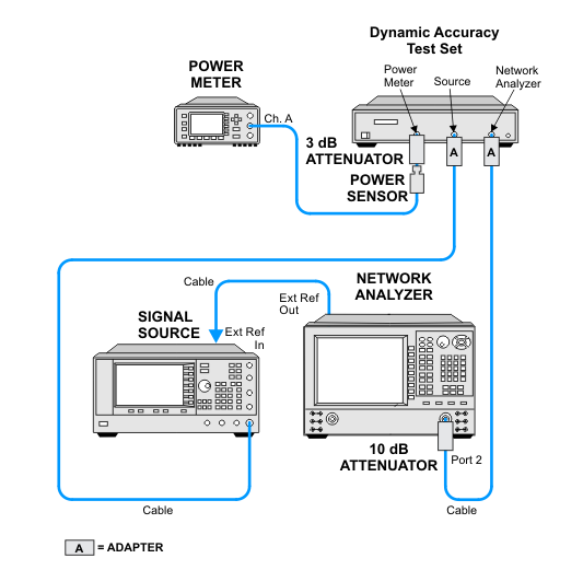
Connection Setups
|
|
Due to the complexity of the PNA family of analyzers, the following notes apply to illustrations in the PNA Help:
- Only a single representative PNA model will be shown. Therefore, port locations may differ in older PNA models than what is shown in the illustration. Refer to the port labels on the UUT.
- Some illustrations may differ than those in TME.
- If the test procedure applies to multiple ports, illustrations may show the setup on only one test port.
- Setups for some option configurations may not appear in the Help.
|
Noise Receiver Linearity Test Setup
Alternate Solution, Normal Variant