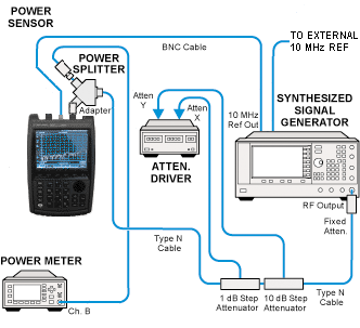
All adjustments will require the CFG Option. Refer to the CFG Option section for more information.
|
|
All adjustments will require the CFG Option. Refer to the CFG Option section for more information. |
This adjustment determines gain compensation factors for each of 32 settings for the RF IN attenuator. Gain measurements are performed at approximately 15 frequencies, at least one in each SA band. There are 32 compensation factors for each measured frequency.
|
Related test: |
none |
Mode where used: SA
|
Test Equipment |
Recommended Model Number |
|---|---|
|
Signal Generator #1 |
E8257D with options:
|
|
Attenuator/Switch Driver |
11713B Opt 001/024/060/101 |
|
Attenuator, 6 dB fixed |
8491A Opt 006 |
|
Attenuator, 1 dB step |
8494G Opt 001/024 |
|
Attenuator, 10 dB step |
8496G Opt 001/024 |
|
Power Meter |
N1914A |
|
Power Sensor |
E9304A Opt H18 |
|
Power Splitter |
11667A |
|
Power Sensor Cable |
11730A |
|
BNC Cable |
8120-2582 |
|
Type-N Cable |
11500C |
|
Attenuator control cable |
8120-2703 |
|
|
The following notes apply to illustrations in the FieldFox Help:
|

