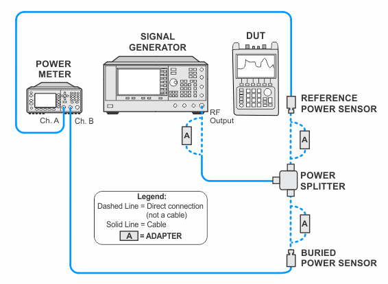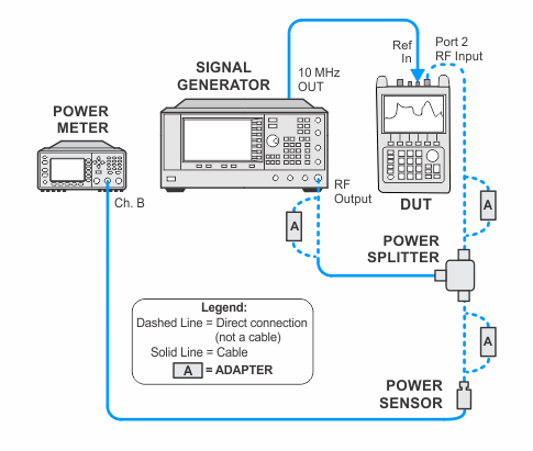
The Total Absolute Amplitude Accuracy specification requires very tight measurement uncertainties for this test. Consequently, the splitter and power sensors used in this test must be 26.5 GHz, 3.5 mm.
N9936A/37A/38A
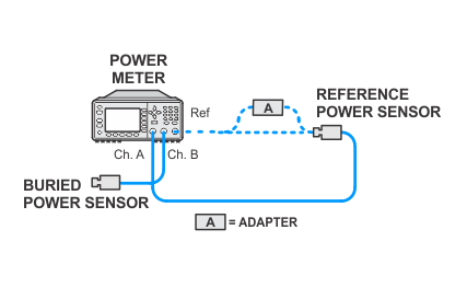
In this test a signal is split and applied to the DUT and to a power meter. The absolute amplitude accuracy is the difference between the power meter reading and the FieldFox reading. A "buried power sensor" technique is used to characterize the tracking error of a power splitter in order to avoid the relatively large specified tracking error. The buried sensor calibration essentially trades power meter errors for splitter tracking errors.
This test checks frequencies above 9 GHz.
|
Test type: |
performance |
|
Related specification: |
Total Absolute Amplitude Accuracy |
|
Related adjustment: |
|
Test Equipment |
Recommended Model Number |
|---|---|
|
Signal Generator #1 |
E8257D with options:
|
|
Power Meter |
N1914A |
|
Power Sensor |
N8485A |
|
Power Splitter, 3.5 mm |
11667B |
|
Cable, power sensor |
11730A |
|
Cable, BNC |
8120-2582 |
|
Cable, 3.5 mm (m) to 3.5 mm (m) |
11500E |
|
Adapter, Type-N (m) to 3.5 mm (m) |
1250-1744 |
|
Adapter, 3.5 mm (f) to 3.5 mm (f)
|
83059B |
|
Adapter, 2.4 mm (f) to 3.5 mm (f)
|
11901B |
|
|
The Total Absolute Amplitude Accuracy specification requires very tight measurement uncertainties for this test. Consequently, the splitter and power sensors used in this test must be 26.5 GHz, 3.5 mm. |
|
|
The following notes apply to illustrations in the FieldFox Help:
|


